Explanation of the term GND/Ground
I/O devices always have a reference potential somewhere. After all, the working voltage is only created by two points having different potentials – one of these points is then called the reference potential.
In the Beckhoff I/O area and in particular with the analog products, various reference potentials are used and named. These are defined, named and explained here.
Note: for historical reasons, different names are used with various Beckhoff I/O products. The following explanations place them on a uniform foundation.
SGND
- Also called: FE, Functional Earth, Shield GND, Shield.
- Use: Dissipation of interference and radiation, predominantly currentless.
- Symbol:
 .
. - Notes and recommendations on SGND/FE can be found in the separate chapter
Notes regarding analog equipment - shielding and earth. - SGND usually ends at the structural earth star point.
- In order to be usable for its intended purpose, SGND itself should be a low noise/noise-free "clean" current and voltage sink.
PE
- Also called: Protective Earth.
- Use: Protective measure to prevent the occurrence of hazardous touch voltages by dissipating these touch voltages and then tripping upstream protective devices. If installed correctly, the PE conductor is currentless, but according to specification it must be capable of conducting for the protection case.
- Symbol:
 .
. - PE usually ends at the structural earth star point.
- For specifications and notes on PE, please refer to the relevant rules.
PGND, AGND
- Use: Reference ground or return line of analog or digital signals.
- Depending on use, nominally currentless as reference potential or conducting as return line.
- In the analog area, the so-called standard signals can be 0...10 V and 4...20 mA, measuring bridge signals and thermocouples can be in the range of a few mV and resistance measurement in any Ohm range, and voltages can be from µV to a few thousand Volts.
- In the digital area they can be, for example, 0/24 V, -5/+5 V etc.
- Symbols:
preferred: ;
;
hardly used any more, but actually means earth potential: .
. - There may be several PGND/AGND networks in a system that are electrically isolated from one another.
- If a device has several AGNDs, due to isolation by channel, these can be numbered: AGND1, AGND2, …
- PGND
- also called: GNDPC, 0 V, power contact 0 V, GND.
- Version: PGND is a structural description of the "negative" power contact rail of the Bus Terminal system.
- Can be connected to the device electronics, for example for supplying power to the device or as a signal feedback (see chapter Single-ended/differential typification). Refer to the respective device documentation.
- Example: PGND is not connected to the device electronics:
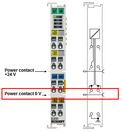 .
. - AGND
- Also called: GNDint, GND, analog ground, GNDanalog.
- AGND electrically designates the device's analog reference ground.
- AGND can, for example, be internally connected to PGND or to a connection point so that it can be connected externally to a desired potential. Electrical restrictions according to the device documentation must be observed, e.g. common mode limits.
- AGND is usually a currentless reference potential. The action of interference on AGND must be avoided.
- Example: AGND is fed out on the device plug:
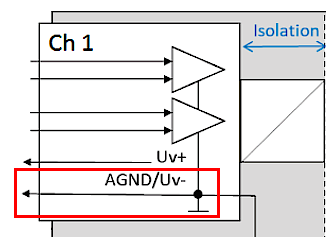 .
.