Single-ended/differential typification
For analog inputs Beckhoff makes a basic distinction between two types: single-ended (SE) and differential (DIFF), referring to the difference in electrical connection with regard to the potential difference.
The diagram shows two-channel versions of an SE module and a DIFF module as examples for all multi-channel versions.
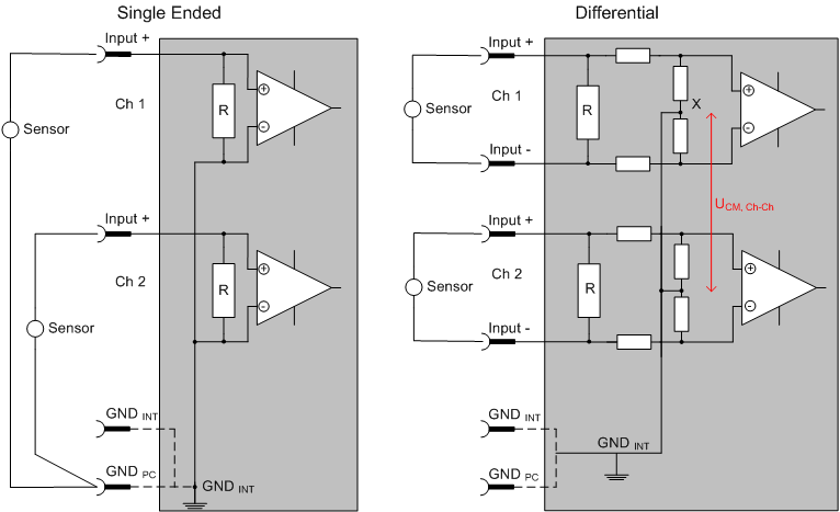
Note: Dashed lines indicate that the respective connection may not necessarily be present in each SE or DIFF module. Electrical isolated channels are operating as differential type in general, hence there is no direct relation (voltaic) to ground within the module established at all. Indeed, specified information to recommended and maximum voltage levels have to be taken into account.
The basic rule:
- Analog measurements always take the form of voltage measurements between two potential points.
For voltage measurements a large R is used, in order to ensure a high impedance. For current measurements a small R is used as shunt. If the purpose is resistance measurement, corresponding considerations are applied. - Beckhoff generally refers to these two points as input+/signal potential and input-/reference potential.
- For measurements between two potential points two potentials have to be supplied.
- Regarding the terms “single-wire connection” or “three-wire connection”, please note the following for pure analog measurements: three- or four-wire connections can be used for sensor supply, but are not involved in the actual analog measurement, which always takes place between two potentials/wires.
In particular this also applies to SE, even though the term suggest that only one wire is required. - The term “electrical isolation” should be clarified in advance.
Beckhoff IO modules feature 1..8 or more analog channels; with regard to the channel connection a distinction is made in terms of: - how the channels WITHIN a module relate to each other, or
- how the channels of SEVERAL modules relate to each other.
The property of electrical isolation indicates whether the channels are directly connected to each other.- Beckhoff terminals/ boxes (and related product groups) always feature electrical isolation between the field/analog side and the bus/EtherCAT side. In other words, if two analog terminals/ boxes are not connected via the power contacts (cable), the modules are effectively electrically isolated.
- If channels within a module are electrically isolated, or if a single-channel module has no power contacts, the channels are effectively always differential. See also explanatory notes below. Differential channels are not necessarily electrically isolated.
- Analog measuring channels are subject to technical limits, both in terms of the recommended operating range (continuous operation) and the destruction limit. Please refer to the respective terminal/ box documentation for further details.
Explanation
- differential (DIFF)
- Differential measurement is the most flexible concept. The user can freely choose both connection points, input+/signal potential and input-/reference potential, within the framework of the technical specification.
- A differential channel can also be operated as SE, if the reference potential of several sensors is linked. This interconnection may take place via the system GND.
- Since a differential channel is configured symmetrically internally (cf. Fig. SE and DIFF module as 2-channel variant), there will be a mid-potential (X) between the two supplied potentials that is the same as the internal ground/reference ground for this channel. If several DIFF channels are used in a module without electrical isolation, the technical property VCM (common-mode voltage) indicates the degree to which the mean voltage of the channels may differ.
- The internal reference ground may be accessible as connection point at the terminal/ box, in order to stabilize a defined GND potential in the terminal/ box. In this case it is particularly important to pay attention to the quality of this potential (noiselessness, voltage stability). At this GND point a wire may be connected to make sure that VCM,max is not exceeded in the differential sensor cable.
If differential channels are not electrically isolated, usually only one VCM, max is permitted. If the channels are electrically isolated this limit should not apply, and the channels voltages may differ up to the specified separation limit. - Differential measurement in combination with correct sensor wiring has the special advantage that any interference affecting the sensor cable (ideally the feed and return line are arranged side by side, so that interference signals have the same effect on both wires) has very little effect on the measurement, since the potential of both lines varies jointly (hence the term common mode). In simple terms: Common-mode interference has the same effect on both wires in terms of amplitude and phasing.
- Nevertheless, the suppression of common-mode interference within a channel or between channels is subject to technical limits, which are specified in the technical data.
- Further helpfully information on this topic can be found on the documentation page Configuration of 0/4..20 mA differential inputs (see documentation for the EL30xx terminals, for example).
- Single Ended (SE)
- If the analog circuit is designed as SE, the input/reference wire is internally fixed to a certain potential that cannot be changed. This potential must be accessible from outside on at least one point for connecting the reference potential, e.g. via the power contacts (cable).
- In other words, in situations with several channels SE offers users the option to avoid returning at least one of the two sensor cables to the terminal/ box (in contrast to DIFF). Instead, the reference wire can be consolidated at the sensors, e.g. in the system GND.
- A disadvantage of this approach is that the separate feed and return line can result in voltage/current variations, which a SE channel may no longer be able to handle. See common-mode interference. A VCM effect cannot occur, since the module channels are internally always 'hard-wired' through the input/reference potential.
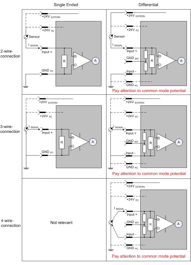
Typification of the 2/3/4-wire connection of current sensors
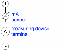
Current transducers/sensors/field devices (referred to in the following simply as ‘sensor’) with the industrial 0/4-20 mA interface typically have internal transformation electronics for the physical measured variable (temperature, current, etc.) at the current control output. These internal electronics must be supplied with energy (voltage, current). The type of cable for this supply thus separates the sensors into self-supplied or externally supplied sensors:
Self-supplied sensors
- The sensor draws the energy for its own operation via the sensor/signal cable + and -.
So that enough energy is always available for the sensor’s own operation and open-circuit detection is possible, a lower limit of 4 mA has been specified for the 4-20 mA interface; i.e. the sensor allows a minimum current of 4 mA and a maximum current of 20 mA to pass. - 2-wire connection see Fig. 2-wire connection, cf. IEC60381-1
- Such current transducers generally represent a current sink and thus like to sit between + and – as a ‘variable load’. Refer also to the sensor manufacturer’s information.
Therefore, they are to be connected according to the Beckhoff terminology as follows:
preferably to ‘single-ended’ inputs if the +Supply connections of the terminal/ box are also to be used - connect to +Supply and Signal
they can, however, also be connected to ‘differential’ inputs, if the termination to GND is then manufactured on the application side – to be connected with the right polarity to +Signal and –Signal
It is important to refer to the information page Configuration of 0/4..20 mA differential inputs (see documentation for the EL30xx terminals, for example)!
Externally supplied sensors
- 3- and 4-wire connection see Fig. Connection of externally supplied sensors, cf. IEC60381-1
- the sensor draws the energy/operating voltage for its own operation from two supply cables of its own. One or two further sensor cables are used for the signal transmission of the current loop:
- 1 sensor cable: according to the Beckhoff terminology such sensors are to be connected to ‘single-ended’ inputs in 3 cables with +/-/Signal lines and if necessary FE/shield
- 2 sensor cables: for sensors with 4-wire connection based on +supply/-supply/+signal/-signal, check whether +signal can be connected to +supply or –signal to –supply.
- - Yes: then you can connect accordingly to a Beckhoff ‘single-ended’ input.
- - No: the Beckhoff ‘differential’ input for +Signal and –Signal is to be selected; +Supply and –Supply are to be connected via additional cables.
It is important to refer to the information page Configuration of 0/4..20 mA differential inputs (see documentation for the EL30xx terminals, for example)!
Note: expert organizations such as NAMUR demand a usable measuring range <4 mA/>20 mA for error detection and adjustment, see also NAMUR NE043.
The Beckhoff device documentation must be consulted in order to see whether the respective device supports such an extended signal range.
Usually there is an internal diode existing within unipolar terminals/ boxes (and related product groups), in this case the polarity/direction of current have to be observed.
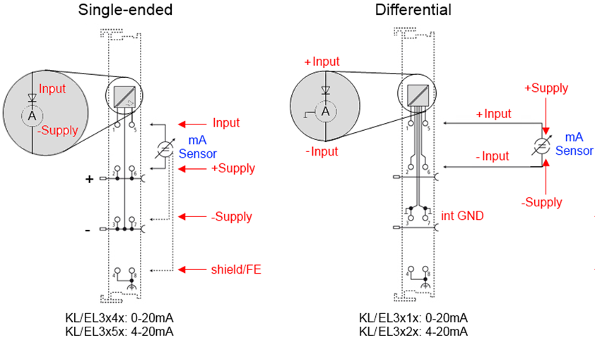
Classification of the Beckhoff terminals/ boxes - Beckhoff 0/4-20 mA terminals/ boxes (and related product groups) are available as differential and single-ended terminals/ boxes (and related product groups):
Single-ended EL3x4x: 0-20 mA, EL3x5x: 4-20 mA; KL and related product groups exactly the same |
| Differential EL3x1x: 0-20 mA, EL3x2x: 4-20 mA; KL and related product groups exactly the same |
Preferred current direction because of internal diode |
| Preferred current direction because of internal diode |
Designed for the connection of externally-supplied sensors with a 3/4-wire connection |
| The terminal/ box is a passive differential current measuring device; passive means that the sensor is not supplied with power. |
Designed for the connection of self-supplied sensors with a 2-wire connection |
|
|