Basic function principles
The high-precision KL3172 analog input terminals can measure two voltages (KL3132, KL3162, KL3172, KL3182) or two currents (KL3142, KL3152) and display them with a resolution of 16 bits (65535 steps). High-precision measurements are ensured through cyclic self-calibration.
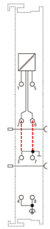
By default, the inputs are switched as differential inputs. For terminals KL3132, KL3162, KL3172 and KL3182, terminal point -E1 of the first channel can be switched to internal analog ground with bit R32.6 of the feature register.
Specification
The specification values are valid after at least 30 minutes warm-up time. The self-calibration largely compensates for internal drifts, but the internal reference (like any electronic component) is slightly temperature dependent and must stabilize.
The channels of the KL31x2 are not electrically isolated. Note CommonMode effects.
Process data
Analog values are represented as follows:
Input signal | Value | ||||||
|---|---|---|---|---|---|---|---|
KL3142-0000 | KL3152-0000 | KL3162-0000 | KL3172-0000 | KL3172-0500 | KL3172-1000 | dec | hex |
0 mA | 4 mA | 0 V | 0 V | 0 V | 0 V | 0 | 0x0000 |
20 mA | 20 mA | 10 V | 2 V | 500 mV | 1 V | 65535 | 0xFFFF |
Input signal | Value | ||||||
KL3132-0000 | KL3182-0000 | dec | hex | ||||
-10 V | -2 V | -32768 | 0x8000 | ||||
+10 V | +2 V | +32767 | 0x7FFF | ||||
Calculation
The terminal continuously records measured values and stores the raw values of its A/D converter in register R0 (RAM). After each acquisition of the analog signal, a correction is calculated using the compensation and, if necessary, calibration values. This is followed by manufacturer and user scaling:
YA = (XADC + BA) x AA | (1.0) | Manufacturer compensation (if calibration inactive) |
YA = ((XADC + BK) x AA) x (AGK / AK) | (1.1) | Manufacturer compensation / calibration (if calibration activated) |
YH = YA x AH + BH | (1.2) | Manufacturer scaling |
Yoff = YH x AW + BW | (1.3) | User scaling |
Legend
Name | Name | Unit | Register |
|---|---|---|---|
XADC | Output value of the A/D converter | [1] | - |
Yoff | Process data for controller | [1] | - |
BA | Vendor calibration: offset (can be deactivated via bit R32.5 of the feature register) | [1] | |
AA | Vendor calibration: gain (always active) | [1 x 2-16 + 1] | |
BK | Calibration: offset (can be activated via bit R32.5 of the feature register) | [1] | |
AK | Calibration: gain (can be activated via bit R32.5 of the feature register) | [1] | |
AGK | Basic calibration: gain (can be activated via bit R32.5 of the feature register) | [1] | |
BH | Vendor scaling: offset (can be activated via bit R32.1 of the feature register) | [1] | |
AH | Vendor scaling: gain (can be activated via bit R32.1 of the feature register) | [1 x 2-8 + 1] | |
BW | User scaling: offset (can be activated via bit R32.0 of the feature register) | [1] | |
AW | User scaling: gain (can be activated via bit R32.0 of the feature register) | [1 x 2-8 + 1] |
Calibration
The analog channels are periodically subjected to self-calibration. In this process, the field signal is electrically separated from the internal acquisition (ADC); instead, internal reference voltages are applied and thus essential circuit parts are acquired. Only the near-field interference suppression elements (L/C combination) and the analog switches themselves cannot be acquired. The aim is to compensate for temperature drift effects.
Note | |
External effect of the field separation The described separation of the internal circuit from the signal can cause interferences on the field signal! With normal, i.e. switched on measurement, a current flows through the KL31x2 in any case, which applies a load to the source. This is omitted while the terminal is in self-calibration. If necessary, check the behavior of the signal source (sensor, calibrator) with a separate measuring device in the load change moments, whether overvoltages/undervoltages or short-term glitches/peaks occur. |
The calibration interval is set in register R40 in steps of 100 ms. During calibration
- no current process data are present. Value 0 is present.
- the terminal sets the SB1.6 in the status byte
- the RUN LED (green) is extinguished and Error (red) is set
Calibration can be disabled by the controller via control byte CB1.1 if necessary. If calibration is disabled over a prolonged period, the terminal carries out a forced calibration, in order to compensate any voltage drifts that may be caused by changes in temperature. The forced calibration interval is specified via register R44 as a multiple of the calibration interval. If a further calibration between two cycles is required, this can be started manually by setting bit CB1.0. The terminal then acts as if it had triggered a calibration itself.
 | Fluctuating measuring signals interfere with self-calibration In the calibration phase, the terminal uses a stabilization check to verify that the input signal is stable. Strongly fluctuating measuring signals prevent a termination of the self-calibration, it stops with Error=1 and Overload/Underload=1, see chapter If such a signal is expected at the system, the following can be selected
|
The functionality of the calibration including all features invariably refers to both channels simultaneously! The channels cannot be calibrated individually. For this reason, the registers R40, R44, R47 and R48 are only implemented once for both channels.
- In the first phase of the calibration, an input voltage of 0 V is applied to both analog inputs (zero calibration). The zero points of both analog input stages can be determined in this way. For this measurement, the respective absolute value of the channels is of interest. The value is subsequently stored in the RAM (register R1).
- During the second calibration phase, an internal reference voltage of approx. 1.8 V (final calibration) is applied to both analog inputs. In this case, it is no longer the absolute value of the measurement result that is of interest, but only any deviation from the basic calibration value determined during production (register R23). The ratio between the two values is calculated and used in the next correction calculation. The value is subsequently stored in the RAM (register R2).
Stabilization of the calibration
During the calibration, a stabilization of the offset and gain values is carried out. The calibration values are only accepted once a certain number (specified via register R47) of measured values is inside a certain tolerance range (specified via register R48). This further increases the precision. This function can be deactivated via bit R32.7 .
Limit values
The terminal offers the option of monitoring two limit values per channel. Limit value 1 can be specified via register R35, and limit value 2 via register R36. They are activated via bits in the feature registers R32.9 and R32.10. The status of the current process data value is indicated to the controller via the status byte SB1. Possible states are: Process data equal limit value (3), process data less than limit value (2), process data greater than limit value (1).
Limiting the measuring range
The terminal indicates any violation of the measuring range to the higher-level controller via the status byte.
- If the current measured value is larger than 0xFFFF or 0x7FFF, bit SB1.1 is set.
- Is the current measured value is less than 0 or 0x8000, bit SB1.0 is set.
In both cases, the ERROR LED of the respective channel will be on. This function can be deactivated via bit R32.8.
Differential measurement
With the KL3132, KL3162, KL3172, KL3182, the differential measurement can be deactivated with bit R32.6. Then, for channels 1 and 2, the input is internally switched to GND at terminal point 3/7, which must then be wired externally accordingly.