Self-adjustment
The stepper motor terminal has an option for simple, "on the fly" self-alignment. A linear axis provides a useful platform for this purpose.
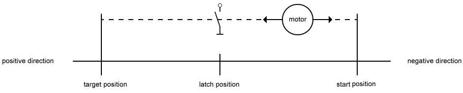
A switch positioned on the path serves as triggering sensor. If it is activated, it triggers a latch event in the terminal (any latch input can be used for this purpose).
Initially, the latch value is used as reference position. If the triggering sensor is activated again and a latch value is saved, at the next standstill the terminal corrects the difference between the reference position and the value latched during service operation. The procedure is described in more detail in the sample below.
Sample
The following sample illustrates self-alignment.
- In the control byte, set bit CB.0 to 1 for enabling motor control.
- Use register communication to enter the command 0x0530 in register R7, in order to activate self-adjustment.
- Activate a latch event in the control word using bits CW.0 to CW.4, in order to latch the reference position.
- Enter a velocity value in the process data word DataOUT, in order to move the motor to the reference position.
- The terminal sets bit SW.4 when the reference position was passed.
- Set the velocity in the process data word DataOUT to zero and clear the latch enable (at this point the reference position is saved).
- Enter an opposite velocity value in the process data word DataOUT, in order to move the motor back to the home position.
- When the home position is reached, in the control word activate the latch event that was previously used for referencing.
- Now use process data communication to enter a velocity value in DataOUT, in order to move the motor to the latch point again.
- Use process data communication to set the velocity to zero and clear the latch enable (the current position is now corrected).
- Use register communication to enter the stop command 0x0540 in register R7, in order to activate self-adjustment.