Wiring of differential current inputs
This chapter is based on the previous explanations and considers the common-mode theme with respect to (differential) current measurement by shunt (integrated measuring resistance).
Shunt current measurement inputs are generally electrically connected to the current circuit. If the measuring device (e.g. analog input terminal) has multiple channels that are not electrically isolated from one another, the potential references must be considered with this measurement application as well.
The following decision tree can be followed:
- For electrically isolated current measuring channels, the specified insulation strength must be observed. In principle, such channels measure differentially on two poles between input and output; a Ucm consideration is not necessary.
- If the channels are not electrically isolated (i.e. they have a common reference ground inside the device) and are
- single-ended (this means that one channel pole in the device is forcibly connected to a special potential, e.g. negative power contact and this applies to all channels in the device),
→ then no Ucm consideration is necessary here either; only the maximum voltage applied across the shunt needs to be compared to the channel specification - differential (this means that both poles are freely selectable and accessible)
→ a Ucm consideration is necessary because, depending on the external potentials, a CMP that may be impermissible (see previous chapter) may arise internally. UCM, max may not be exceeded on any of the channels inside the device.
If UCM, max of an analog input channel is exceeded, this may result in significantly incorrect measurements due to internal equalizing currents.
In order to consider the theoretical considerations with numbers, here is a
Consideration using a differential 20 mA measurement with the EL30xx/EL31xx as an example
Notice | |
Numerical values in the example The numerical values used in the following should be regarded as examples; please refer to the corresponding device documentation for specific statements on the products considered. |
- The EL301x, EL302x, EL311x and EL312x are designed for differential 20 mA measurement, i.e. a specific potential reference is not necessary (but recommended!).
- The individual terminal is regarded here as the system limit.
- The current is measured via a 33 Ω shunt per channel, consequently there is a maximum voltage drop of 660 mV across the shunt at 20 mA
- Additional internal resistor arrangement (voltage divider, protective resistors) with GND point (A) central to the shunt.
The layout of the resistors is so symmetrical that the potential of (A) comes to rest centrally with respect to the voltage drop across the shunt. - The central point of the voltage dropping across the 33 Ω shunt is termed the common-mode measurement point (CMP).
According to the technical data for the product, the maximum permissible UCM voltage (common mode) is referenced to the potential between the CMP of a channel and the internal GND or to the potential between the CMP of two channels inside a terminal.
It must not exceed the specified limit (typically ±10 or ±35 V). - The common GNDint potential (A) is
- fed to a terminal point in the case of 1- and 2-channel terminals from the above series and not connected to GNDPC (power contact); it is thus freely selectable and connectable from outside The UCM specification can thus be complied with through the wiring of this GND point to suit the application, making it possible to use this device even with atypical sensor wiring.
- connected to GNDPC in the case of 4-channel terminals and is thus not freely selectable.
- This GND potential GNDint is common for all channels implemented in the terminals.
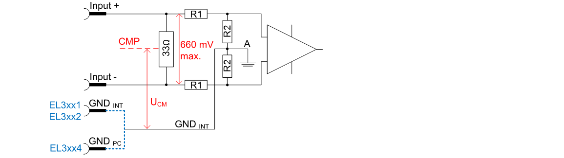 Fig.60: Internal connection wiring of a 20 mA channel in the above series, R1/2 e.g. 10 kΩ
The connected GND points inside the terminal can be seen in the block diagram of a 2-channel terminal (Fig. Internal connection wiring of two 20 mA channels from the above series):
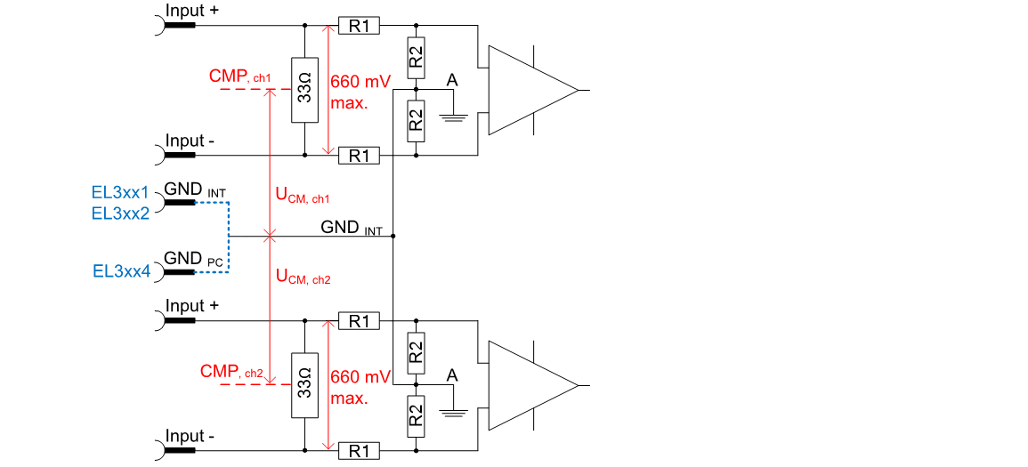 Fig.61: Internal connection wiring of two 20 mA channels from the above series
Below, various wiring options are considered with regard to their admissibility in respect of the CMP. It is assumed that the current sensors output 100% output end value, i.e. 20 mA.
Example 1a
The 2-channel EL3012 is wired with two sensors that are supplied from 5 and 24 V. Both current measurements are executed as low-side measurements. This type of connection is permissible, because CMPch1 and CMPch2 each lie around 330 mV above 0 V at Imax; UCM is thus always < 0.5 V. UCM < 10 V is thus complied with (applies to EL30xx).
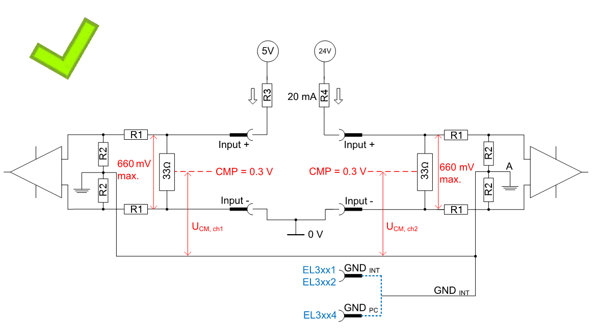 Fig.62: Example 1a: Low-side measurement (R3 = 250 Ω, R4 = 1200 Ω)
If GNDint is not externally wired in the case of the EL30x1/EL30x2 or EL31x1/EL31x2, the potential on GNDint can settle according to necessity – it "floats". Please note that reduced measuring accuracy is to be expected for this mode.
Example 1b
This also applies accordingly if the floating point GNDint is pulled to a different potential.
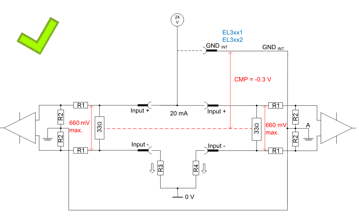 Fig.63: Example 1b, high-side measurement (R3 = R4 = 1200 Ω)
Example 2a
The same EL3012 is now wired again with the two 20 mA sensors, but this time once in low-side measurement at 5 V and once in high-side measurement at 12 V. This produces a considerable potential difference UCM > 10 V between the two channels. If UCM,max were to be 10 V, this would not be permissible (observe the respective device specification!)
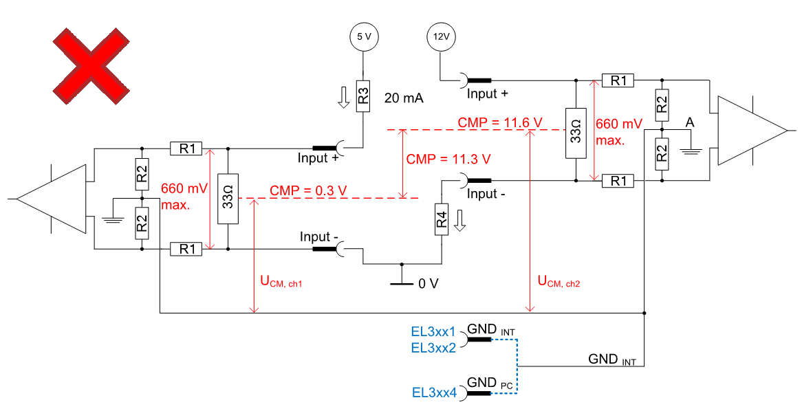 Fig.64: Example 2a, impermissible high-side/low-side measurement (R3 = 250 Ω, R4 = 600 Ω)
As a remedy, GNDint could be connected in this case with an auxiliary potential of 6 V referenced to "0 V". A/GNDint thus settles approx. in the middle between 0.3 V and 11.6 V.
Example 2b
In the EL3xx4, GNDint is connected internally with the negative power contact. The choice of potential is therefore limited.
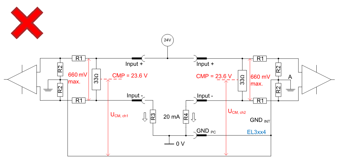 Fig.65: Example 2b, impermissible EL3xx4 wiring (R3 = R4 = 1200 Ω)
The CMP settles at 23.6 V and thus >> 10 V.
Summary
This results in precise specifications for the external wiring of differential current inputs with 20 mA sensors:
- It is recommended if possible to connect GNDint to a low-impedance, interference-free potential, as this significantly improves the measuring accuracy.
Observe the notes on the potential reference UCM! - The potential reference CMP < UCM,max must be complied with, both between CMP ↔ GNDint and between CMPch(x) ↔ CMPch(y).
If this cannot be guaranteed, single-channel variants or multi-channel variants with electrical isolation must be used. - If the sensor cable is shielded, it must not be connected to the GNDint terminal point, but to a low-impedance shielding point provided for the purpose.