Default settings and information
Process data information
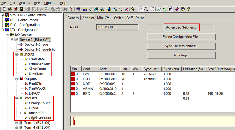 Fig.167: Process data
The EtherCAT master features info data which provide up-to-date cycle diagnostics (yellow variables) and general information outside the real-time context (green variables). The main parameters are described below:
- DevState: target = 0; all slaves are then in OP state, with no link errors etc.
-
Frm0WcState: should also be 0. Such a variable (Frm0WcState, Frm1WcState, ...) is created for each cyclic Ethernet frame
As a minimum, an application should check and monitor these two master inputs during each cycle. - AmsNetId: the application (PLC, external task) requires this AMS address for addressing the EtherCAT master or the subordinate slaves via ADS.
Further options are available via Advanced Settings:
Master settings
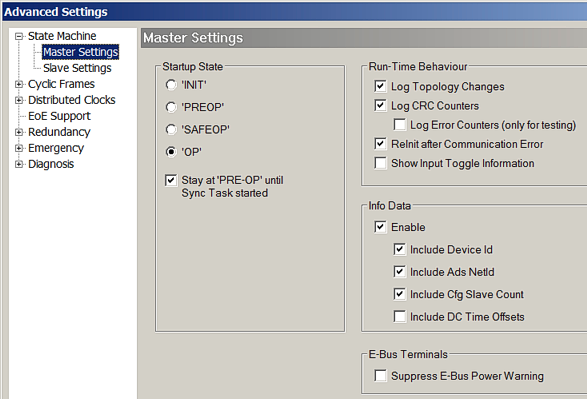 Fig.168: Master settings
|
Element |
Detail |
Explanation |
Effects |
|---|---|---|---|
|
StartUp State |
|
As soon as TwinCAT is “started” (RUN or Config/FreeRun), the master assumes the state selected here. The transition to OP only takes place once the Sync Task has started. If several tasks run on a system, the Sync Task which includes the distributed control has the highest priority. DC-capable slaves cannot be switched to OP if their local clock is not adjusted properly, or they may come out of OP state again if the control does not succeed (“Sync lost”). |
It is recommended to set and monitor the EcMaster state from the application (PLC, as available), (FB_EcGet/SetMasterState from TcEtherCAT.lib). This enables the master to assume OP even after serious communication errors. |
|
Run-Time behavior |
Log Topology Changes |
Activated by default Online outputs in the logger window are activated |
Deactivation not sensible |
|
|
Log CRC counters |
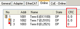
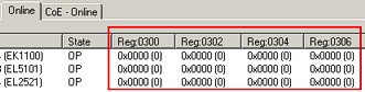
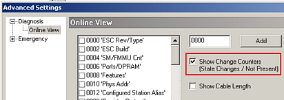
Activated by default. In OnlineView the CRC errors of the slaves are read from the field and accumulated.
|
If the CRC register counters in the slaves are to be displayed in the online view, this option is to be deactivated – i.e. it clears the local x0300ff registers once they have been read in order to prevent overflow at xFF.
|
|
|
Log error counters |
no function |
|
|
|
ReInit after communication error |
After a communication error during which the master has left the OP state (connection disconnected and lost frames for more than 10 cycles, stations switched off) TwinCAT tries to switch the master back to OP state. |
If the EcMaster state is controlled from the application it is essential to disable this option, since otherwise both mechanisms may hinder each other. Both access the master via ADS. |
|
|
Show input toggle information |
If activated, an additional toggle variable is displayed for input terminals, which can be linked. It changes its state 0/1 whenever a new datagram is received. |
|
|
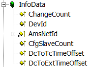
Info data |
|
The display of these (green) non-real-time information data in the System Manager tree can be deactivated here. |
DeviceId: useful for access from the application AdsNetId: required for access from the application CfgSlaveCount: number of changes in the configuration so far Dc time offsets: the offsets between external, internal and TwinCAT clock (which are constant at runtime) are displayed. Required for external EtherCAT synchronization. |
|
E-bus power warning |
|
By default the System Manager issues a warning of the maximum load of an EtherCAT coupler (e.g. EK1100) is about to be exceeded. |
|
Slave settings
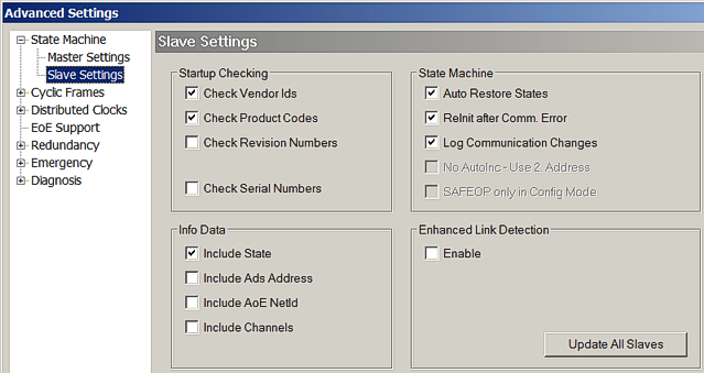 Fig.169: Slave settings
Element | Detail | Explanation | Effects |
|---|---|---|---|
StartUp checking |
| During EtherCAT startup the properties of all slaves activated here are checked. However corresponding slave settings have priority! | By default the VendorID and ProductCode (e.g. El2521-0010) are checked. This is recommended, because it enables devices of the same type but with higher revision number to be used as replacement devices. |
State machine | Auto restore states | If the slave has left the OP for inherent reasons (loss of power, synchronization error), the EtherCAT master tries to put the slave back to OP state or to the last regularly reached state, if the checkbox is activated. | It is recommended to set and monitor the slave state from the application (PLC, if available, FB_EcGet/SetMasterState from TcEtherCAT.lib). This enables the application to control the slave in accordance with the application-specific requirements. Example (servo axis): the EtherCAT master would switch the axis back to OP state as soon as possible, without deeper knowledge of the safety or functional context. On the contrary, the application can decide whether and when the axis should be switched back to OP state after the serious “Failure State” error. Besides, a DeadLock can occur: If the master resets the slave to OP but only reaches SAFEOP before another fault occurs, the master will then only try to put the slave to SAFEOP. OP state can no longer be reached. It is therefore advisable to control the master and slave state through the application. |
| ReInit after Comm.Error | If the communication to a slave was interrupted, the master will restart the slave via the INIT state once the connection has been restored, even if the slave had only returned to the SAFEOP state. Thus ensures proper startup and an explicit state of the slave. | If a slave is restarted from INIT --> OP, the outputs are usually disconnected. |
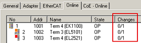
| Log communication changes | Activated by default. State changes are displayed if the option “Show Change Counter” is activated in online view.
| Deactivation not sensible |
Info data |
| The display of these (green) non-real-time information data in the System Manager tree can be (de)activated here. | Showing the ADS address in each slave is useful for linking with a slave-specific FUNCTIONBLOCK that will monitor a slave, for example. |
Enhanced link detection |
| This function is not intended for the general use. | Using this function on EtherCAT devices that do not support it can lead to substantial and irreversible faults in the EtherCAT communication. In devices that support this function it is already activated through the ESI installed during production. |
Sync Task
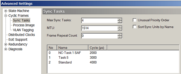 Fig.170: Sync Task
|
Element |
Explanation |
|---|---|
|
Max Sync Task |
TwinCAT 2.10/2.11 supports up to 4 SyncTasks. A SyncTask is a task (PLC, NC) that triggers an I/O update, i.e. with its own EtherCAT frames it communicates with the I/O field using cyclic communication and a fixed cycle time. Fig. Sync Task shows the configuration for 3 active tasks in with cycle times of 2, 3 and 4 ms. Make sure the task prioritization order is correct. If the configuration comprises more than 4 tasks, the tasks with the larger cycle times are set to the slowest task. Hint: This can be useful in cases where a very slow PLC task (> 100 ms) is to be used but the I/O communication has to be faster due to the slave watchdog. In this case the number of “Max Sync Task” should be reduced until only tasks <100 ms remain. |
|
MTU |
The “Max Transfer Unit” (MTU) is the maximum byte length of an Ethernet frame with EtherCAT datagrams. |
|
Frame repeat count |
The TwinCAT EtherCAT master supports multiple sending of EtherCAT frames for the purpose of enhanced interference immunity. |
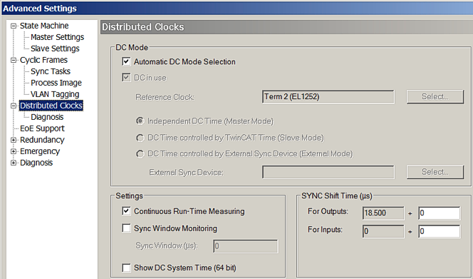 Fig.171: Distributed Clocks
EoE support (Ethernet over EtherCAT)
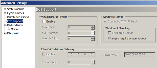 Fig.172: Ethernet over EtherCAT support
|
Element |
Detail |
Explanation |
Effects |
|---|---|---|---|
|
Virtual Ethernet switch |
|
The forwarding of standard TCP/IP traffic via the virtual switch within the TwinCAT EtherCAT system, is automatically set depending on the slaves used. EL6601 devices (SwitchPort terminals) e.g. result in activation of the VirtualEthernetSwitch and adding of ports. (see Fig. "Activating the VirtualEthernetSwitch") For further information please refer to the respective terminal documentations (EL6601, EL6614). |
Explicit activation and specification of ports is required for communication with an intelligent drive via EoE for the purpose of parameterization or firmware updates. In this case a port must be created for each connected device. The number of “Max.Frames” represents the internal queue and can be increased in the event of throughput problems. However, in this case the EtherCAT cycle time and the mailbox-sizes should be checked first. See also EL6601 documentation. |
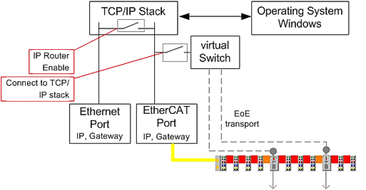 Fig.173: Activating the VirtualEthernetSwitch
|
Element |
Detail |
Explanation |
Effects |
|---|---|---|---|
|
Windows Network |
IP Routing |
See diagram above. |
|
|
EtherCAT mailbox gateway |
|
This setting is required for special slaves. |
|
Cable redundancy
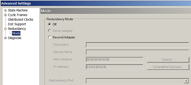 Fig.174: EtherCAT cable redundancy
The options for media redundancy are described in a separate Cable Redundancy section. A TwinCAT Supplement license is required.
If an Ethernet port is entered here (installation real-time-driver see here), the configuration cannot assume RUN state without a license.
Sync Unit assignment
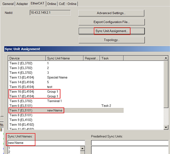 Fig.175: Sync Unit assignment
The Sync Unit assignment only applies to the cyclic data of the EtherCAT system.
By default the System Manager implements a very efficient assignment of cyclic I/O data and sent datagrams. This means as many as possible/all cyclic data are packed in a single/a few datagrams, resulting in low bus load thanks to low telegram overhead. With only a few, in the best case a single datagram as many as possible, in the best case all slaves can be addressed.
The working counter is a diagnostic tool in the EtherCAT system. Each slave that is tasked to process a datagram (writing or reading of data) increases the WorkingCounter (WC). The master sends the datagrams with WC=0 and expects them back with WC>0. By checking the WC the master can immediately detect whether all controlled slaves have processed the datagram correctly. If this is not the case, the master cannot trust the returned data and discards all input data from this datagram. In addition, it commences acyclic diagnostic measures to determine the fault location.
If working counter errors are expected in a system, e.g. because the flexible “HotConnect” topology concept is used, this dialog can be used to allocate coupler modules or individual slaves/terminals to special datagrams, the so-called. SyncUnits. In extreme cases each slaves is allocated a separate datagram, resulting in very inefficient bus utilization since many datagrams and Ethernet frames have to be sent with associated overhead. Note: an Ethernet frame may contain up to 16 EtherCAT datagrams.