TwinCAT 2
Startup
TwinCAT 2 basically uses two user interfaces: the TwinCAT System Manager for communication with the electromechanical components and TwinCAT PLC Control for the development and compilation of a controller. The starting point is the TwinCAT System Manager.
After successful installation of the TwinCAT system on the PC to be used for development, the TwinCAT 2 System Manager displays the following user interface after startup:
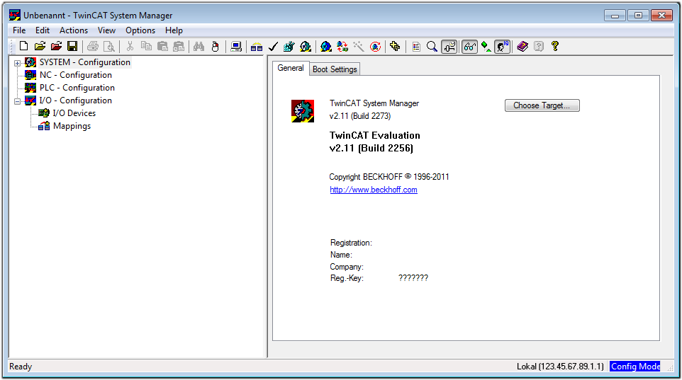 Fig.55: Initial TwinCAT 2 user interface
Generally, TwinCAT can be used in local or remote mode. Once the TwinCAT system, including the user interface (standard) is installed on the respective PLC, TwinCAT can be used in local mode and thus the next step is “Insert Device”.
If the intention is to address the TwinCAT runtime environment installed on a PLC remotely from another system used as a development environment, the target system must be made known first. In the menu under “Actions” → “Choose Target System...”, the following window is opened for this via the symbol “ ” or the “F8” key:
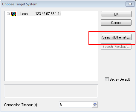 Fig.56: Selection of the target system
Use “Search (Ethernet)...” to enter the target system. Thus another dialog opens to either:
- enter the known computer name after “Enter Host Name / IP:” (as shown in red)
- perform a “Broadcast Search” (if the exact computer name is not known)
- enter the known computer – IP or AmsNetID
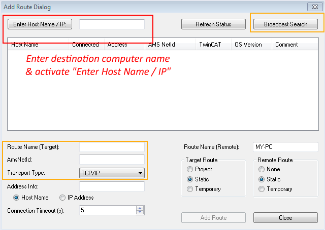 Fig.57: specify the PLC for access by the TwinCAT System Manager: selection of the target system
Once the target system has been entered, it is available for selection as follows (a correct password may have to be entered before this):
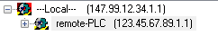
After confirmation with “OK”, the target system can be accessed via the System Manager.
Adding devices
In the configuration tree of the TwinCAT 2 System Manager user interface on the left, select “I/O Devices” and then right-click to open a context menu and select “Scan Devices…”, or start the action in the menu bar via  . The TwinCAT System Manager may first have to be set to “Config Mode” via
  or via the menu
“Actions” → “Set/Reset TwinCAT to Config Mode…” (Shift + F4).
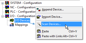 Fig.58: Select “Scan Devices...”
Confirm the warning message, which follows, and select the “EtherCAT” devices in the dialog:
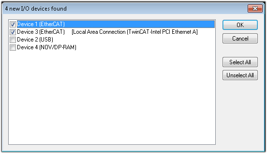 Fig.59: Automatic detection of I/O devices: selection of the devices to be integrated
Confirm the message “Find new boxes”, in order to determine the terminals connected to the devices. “Free Run” enables manipulation of input and output values in “Config Mode” and should also be acknowledged.
Based on the example configuration described at the beginning of this section, the result is as follows:
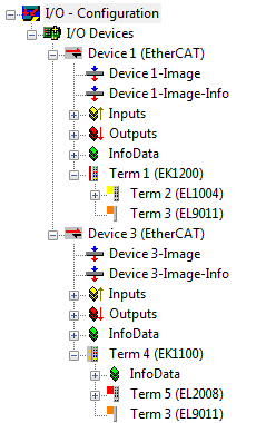 Fig.60: Mapping of the configuration in the TwinCAT 2 System Manager
The whole process consists of two stages, which can also be performed separately (first determine the devices, then determine the connected elements such as boxes, terminals, etc.). A scan (search function) can also be initiated by selecting “Device ...” from the context menu, which then only reads the elements below which are present in the configuration:
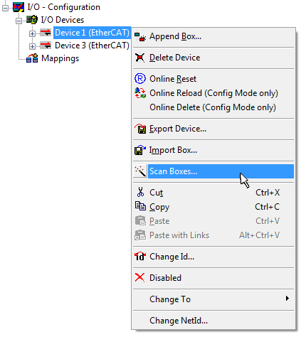 Fig.61: Reading of individual terminals connected to a device
This functionality is useful if the actual configuration is modified at short notice.
Programming and integrating the PLC
TwinCAT PLC Control is the development environment for generating the controller in different program environments: TwinCAT PLC Control supports all languages described in IEC 61131-3. There are two text-based languages and three graphical languages.
- Text-based languages
- Instruction List (IL)
- Structured Text (ST)
- Graphical languages
- Function Block Diagram (FBD)
- Ladder Diagram (LD)
- The Continuous Function Chart Editor (CFC)
- Sequential Function Chart (SFC)
The following section refers solely to Structured Text (ST).
After starting TwinCAT PLC Control, the following user interface is shown for an initial project:
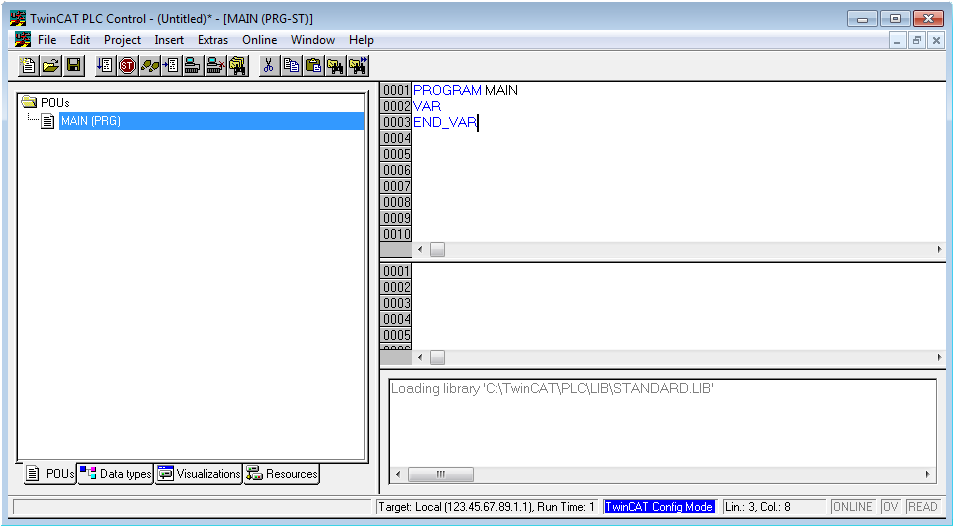 Fig.62: TwinCAT PLC Control after startup
Example variables and an example program have been created and stored under the name “PLC_example.pro”:
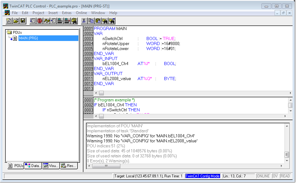 Fig.63: Example program with variables after a compile process (without variable integration)
Warning 1990 (missing “VAR_CONFIG”) after a compile process indicates that the variables defined as external (with the ID “AT%I*” or “AT%Q*”) have not been assigned. After successful compilation, TwinCAT PLC Control creates a “*.tpy” file in the directory in which the project was stored. This file (“*.tpy”) contains variable assignments and is not known to the System Manager, hence the warning. Once the System Manager has been notified, the warning no longer appears.
First, integrate the TwinCAT PLC Control project in the System Manager. This is performed via the context menu of the PLC configuration (right-click) and selecting “Append PLC Project…”:
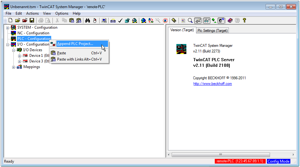 Fig.64: Appending the TwinCAT PLC Control project
Select the PLC configuration “PLC_example.tpy” in the browser window that opens. The project including the two variables identified with “AT” are then integrated in the configuration tree of the System Manager:
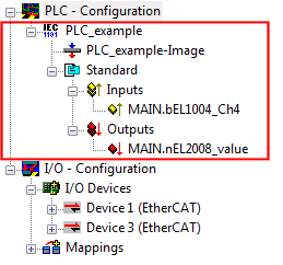 Fig.65: PLC project integrated in the PLC configuration of the System Manager
The two variables “bEL1004_Ch4” and “nEL2008_value” can now be assigned to certain process objects of the I/O configuration.
Assigning variables
Open a window for selecting a suitable process object (PDO) via the context menu of a variable of the integrated project “PLC_example” and via “Modify Link...” “Standard”:
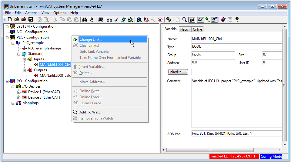 Fig.66: Creating the links between PLC variables and process objects
In the window that opens, the process object for the “bEL1004_Ch4” BOOL-type variable can be selected from the PLC configuration tree:
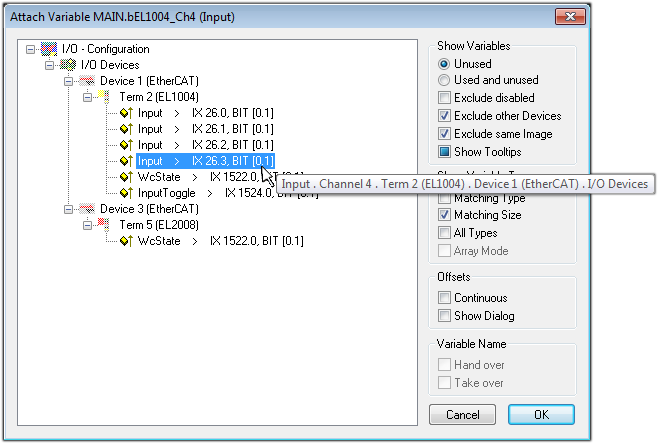 Fig.67: Selecting BOOL-type PDO
According to the default setting, only certain PDO objects are now available for selection. In this example, the input of channel 4 of the EL1004 terminal is selected for linking. In contrast, the checkbox “All types” must be ticked to create the link for the output variables, in order to allocate a set of eight separate output bits to a byte variable in this case. The following diagram shows the whole process:
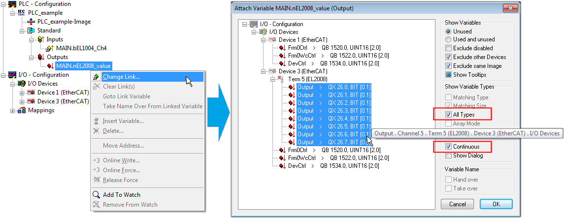 Fig.68: Selecting several PDOs simultaneously: activate “Continuous” and “All types”
Note that the “Continuous” checkbox was also activated. This is designed to allocate the bits contained in the byte of the “nEL2008_value” variable sequentially to all eight selected output bits of the EL2008 Terminal. It is thus possible to subsequently address all eight outputs of the terminal in the program with a byte corresponding to bit 0 for channel 1 to bit 7 for channel 8 of the PLC. A special symbol ( ) on the yellow or red object of the variable indicates that a link exists. The links can also be checked by selecting “Goto Link Variable” from the context menu of a variable. The opposite linked object, in this case the PDO, is automatically selected:
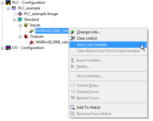 Fig.69: Application of a “Goto Link Variable”, using “MAIN.bEL1004_Ch4” as an example
The process of assigning variables to the PDO is completed via the menu option “Actions” → “Create assignment”, or via  .
.
This can be visualized in the configuration:
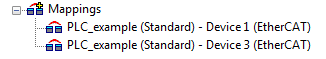
The process of creating links can also be performed in the opposite direction, i.e. starting with individual PDOs to a variable. However, in this example, it would not be possible to select all output bits for the EL2008, since the terminal only makes individual digital outputs available. If a terminal has a byte, word, integer or similar PDO, it is also possible to allocate this to a set of bit-standardized variables. Here, too, a “Goto Link Variable” can be executed in the other direction, so that the respective PLC instance can then be selected.
Activation of the configuration
The allocation of PDO to PLC variables has now established the connection from the controller to the inputs and outputs of the terminals. The configuration can now be activated. First, the configuration can be verified via  (or via “Actions” → “Check Configuration”). If no error is present, the configuration can be activated via
  (or via “Actions” → “Activate Configuration…”) to transfer the System Manager settings to the runtime system. Confirm the messages “Old configurations will be overwritten!” and “Restart TwinCAT system in Run mode” with “OK”.
A few seconds later, the real-time status  is displayed at the bottom right in the System Manager. The PLC system can then be started as described below.
Starting the controller
Starting from a remote system, the PLC control has to be linked with the embedded PC over the Ethernet via “Online” → “Choose Runtime System…”:
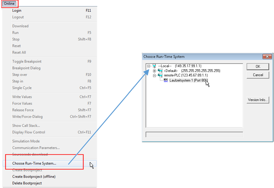 Fig.70: Choose target system (remote)
In this example, “Runtime system 1 (port 801)” is selected and confirmed. Link the PLC with the real-time system via the menu option “Online” → “Login”, the F11 key or by clicking on the symbol  . The control program can then be loaded for execution. This results in the message “No program on the controller! Should the new program be loaded?”, which should be confirmed with “Yes”. The runtime environment is ready for the program start:
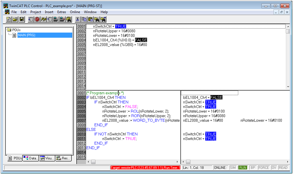 Fig.71: PLC Control logged in, ready for program startup
The PLC can now be started via “Online” → “Run”, F5 key or  .
.