Measurement ±10 V
|
Measurement mode |
±10 V | |||
|---|---|---|---|---|
|
Measuring range, nominal |
-10…+10 V | |||
|
Measuring range, end value (FSV) |
10 V | |||
|
Measuring range, technically usable |
-10.737…+10.737 V | |||
|
PDO resolution (including sign) |
24 bit |
16 bit 2) | ||
|
PDO LSB (Extended Range) |
1.28 µV |
327.68 µV | ||
|
PDO LSB (Legacy Range) |
1.192.. µV |
305.18.. µV | ||
|
Basic accuracy: Measuring deviation at 23°C, with averaging, typ. 6) |
< ±0.015 %, < ±150 ppmFSV < ±1.5 mV | |||
|
Extended basic accuracy: Measuring deviation at 0…55°C, with averaging, typ. 6) |
< ±0.023 %, < ±230 ppmFSV < ±2.3 mV | |||
|
Offset/Zero point deviation (at 23°C) |
EOffset |
< 30 ppmFSV | ||
|
Gain/scale/amplification deviation (at 23°C) |
EGain |
< 140 ppm | ||
|
Non-linearity over the whole measuring range |
ELin |
< 40 ppmFSV | ||
|
Repeatability, over 24 h, with averaging |
ERep |
< 20 ppmFSV | ||
|
Temperature coefficient, typ. |
TcGain |
< 5 ppm/K | ||
|
TcOffset |
< 2 ppmFSV/K < 20 µV/K | |||
|
Input impedance ±Input 1 (internal resistance)
|
Differential typ. approx. 4.12 MΩ || 11 nF CommonMode typ. approx. 40 nF against SGND | |||
Preliminary data:
|
Measurement mode |
±10 V | |||
|---|---|---|---|---|
|
Largest short-term deviation during a specified electrical interference test |
±0.06 % = 600 ppmFSV typ. | |||
|
Common-mode rejection ratio (without filter) |
DC: >115 dB typ. |
50 Hz: >105 dB typ. |
1 kHz: >80 dB typ. | |
|
Common-mode rejection ratio (with 50 Hz FIR filter) 5) |
DC: >115 dB typ. |
50 Hz: >115 dB typ. |
1 kHz: >115 dB typ. | |
|
Noise (without filtering) |
ENoise, PtP |
< 60.0 ppmFSV |
< 469 digits |
< 0.6 mV |
|
ENoise, RMS |
< 10.0 ppmFSV |
< 78 digits |
< 100.0 µV | |
|
Max. SNR |
> 100 dB | |||
|
Noisedensity@1kHz |
< 1.41 | |||
|
Noise (with 50 Hz FIR filter) 5) |
ENoise, PtP |
< 9.0 ppmFSV |
< 70 digits |
< 90.0 µV |
|
ENoise, RMS |
< 1.5 ppmFSV |
< 12 digits |
< 15.0 µV | |
|
Max. SNR |
> 116.5 dB | |||

2) The analog measurement is always done with 24 bits, in 16-bit mode the eight least significant bits are cut off. For further information see chapter “Commissioning”/ “Process data overview”
5) the 50/60 Hz filter setting must be selected via the settings in the CoE depending on the local mains frequency (50 or 60 Hz); the respective nominal mains frequency then applies as the measuring point for common mode rejection or crosstalk.
6) Calculated value according to the equation for estimating usability at the given ambient temperature point or estimating usability over the specified ambient temperature range in operation (Tambient) as stated in chapter "General information on measuring accuracy/measurement uncertainty". In real use, for example at a relatively constant ambient temperature Tambient, a lower (better) achievable uncertainty is attained. A specific calculation according to chapter "General information on measuring accuracy/measurement uncertainty" is recommended, especially if the instrument allows a wider ambient temperature range in operation than 0...55 °C.
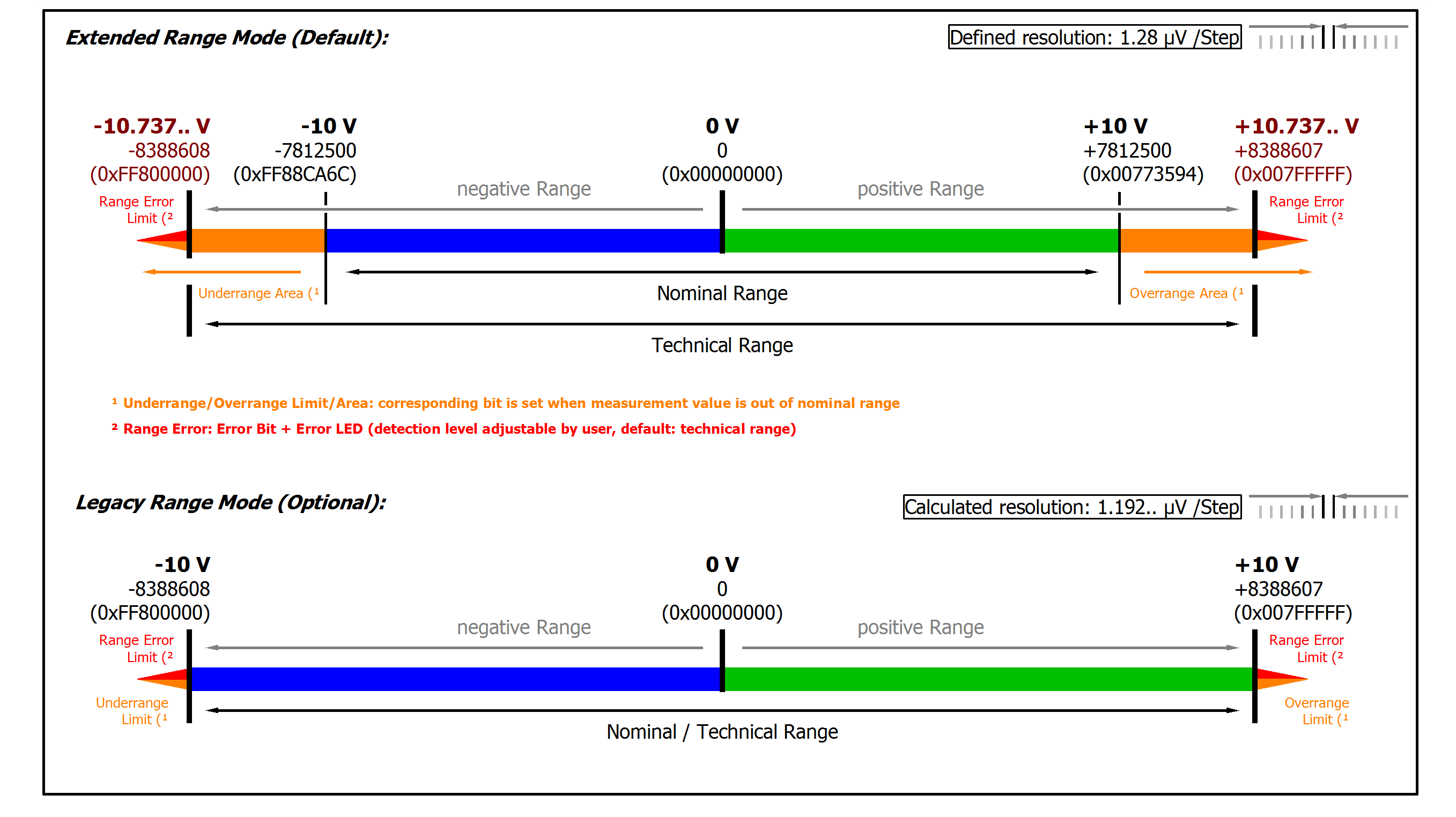 Fig.7: Representation ±10 V measurement range
|
Note: In Extended Range Mode the Underrange/Overrange display in the PDO status has the character of an information/warning when the nominal measuring range is exceeded, i.e. no Error is displayed in the PDO status and LED. If the technical measuring range is also exceeded, Error = TRUE is also displayed. The detection limit for Underrange/Overrange Error can be set in the CoE. In Legacy Range mode, an Underrange/Overrange event also leads to an Error in the PDO status. |