Process data
The System Manager shows the EPI3xxx/ERI3xxx process data which are arranged in the tree structure under the associated Port (A) (in the following example EPI3174-0002 is connected to port 1).
The EPI3174-0002/ERI3174-0002 offer 16-bit status information and the analog value (16 bit) per channel (B) for transmission.
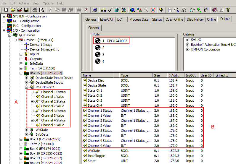
A detailed representation of the structure is obtained by opening the tree structure of the Channel 1 status (see A in the following figure).
Activation of the Show Sub Variables button (C) displays the detailed view of the different bit meanings (see B in the following illustration). The plain text display of the bit meanings is particularly helpful not only in commissioning, but also for linking to the PLC program.
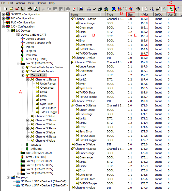
By right-clicking on the Status variable in the configuration tree (A), the structure can be opened for linking. Both the collective name e.g. Channel 1 Status and the individual bit variable e.g. Overrange can be linked, but not both at the same time.
The bit meaning i.e. offset position can then be taken from the memory assignment display (E) on the basis of the point notation, also taking into account the variable size (D).
Example:
163.1 means here that the 1st bit (counting method 0, 1, etc.) or 2nd bit (counting method 1, 2, etc.) in the status word indicates the Overrange. The user requires this information in the PLC if the status word is to be divided into its bit meanings.
Control/status word
Status word
The status word (SW) is located in the input process image, and is transmitted from terminal to the controller.
Bit | SW.15 | SW.14 | SW.13 | SW.12 | SW.11 | SW.10 | SW.9 | SW.8 |
Name | TxPDO Toggle | TxPDO State | Sync error | - | - | - | - | - |
Bit | SW.7 | SW.6 | SW.5 | SW.4 | SW.3 | SW.2 | SW.1 | SW.0 |
Name | - | ERROR | Limit 2 | Limit 1 | Overrange | Underrange | ||
Key
Bit | Name | Description | |
|---|---|---|---|
SW.15 | TxPDO Toggle | 1bin | Toggles with each new analog process value |
SW.14 | TxPDO State | 1bin | TRUE in the case of an internal error |
SW.13 | Sync error | 1bin | TRUE (DC mode): a synchronization error occurred in the expired cycle. |
SW.6 | ERROR | 1bin | General error bit, is set together with overrange and underrange |
SW.5 | Limit 2 | 1bin | See Limit |
SW.4 | 1bin | ||
SW.3 | Limit 1 | 1bin | See Limit |
SW.2 | 1bin | ||
SW.1 | Overrange | 1bin | Analog input signal lies above the upper permissible threshold for this terminal |
SW.0 | Underrange | 1bin | Analog input signal lies under the lower permissible threshold for this terminal |
Control word
The EPI3xxx/ERI3xxx do not have a control word.