Counter
A digital 24 VDC up/down counter input is available in combination with up to two digital inputs/outputs. The function of these inputs/outputs depends on the configuration of SlotGroup 1.
Two of the inputs can also be used as digital 24 VDC outputs, with a current carrying capacity of 0.5 A per channel.
Optionally, one of the outputs can be set when a defined counter value is reached. This allows an exact reaction time independent of the fieldbus cycle.
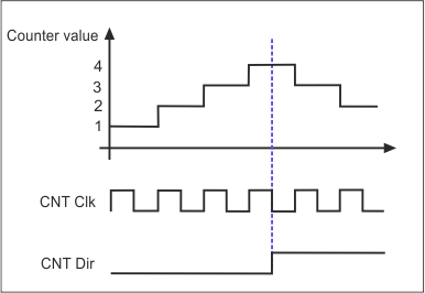
The counting pulses are recorded via the “CNT Clk” input; only the rising edges are counted.
The counting direction is specified via the “CNT Dir” connection point and is defined as follows:
Logic level at “CNT Dir” | Counting direction |
|---|---|
Low | Forward |
High | Backward |
The voltage values of the logic levels can be found in the chapter Counter input.
Notice | |
Bouncing with mechanical switches and buttons When a mechanical switch or push button is actuated, several switching edges can occur, known as bouncing. Depending on the set input filter, these switching edges are counted as pulses by the counter.
|