Process image
| In the default setting the EP8309 is configured for:
|
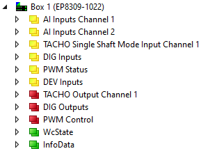
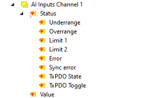
AI Inputs Channel 1 and 2
| The data for the first analog channel can be found under AI Inputs Channel 1.
Underrange: Value of the analog input is less than 0/4 mA or -10/0 V Limit 1: with activated Limit 1 (object 0x8000:07 = 1) means Limit 2: with activated Limit 2 (object 0x8000:08 = 1) means Error: This bit is set if over- or under-range was detected. |
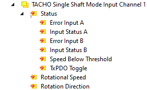
Tacho single-shaft mode (depending on the setting in the PDO assignment)
| The data for the tacho input can be found under TACHO Single Shaft Mode Input Channel 1. see data under commissioning |
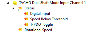
Tacho dual-shaft mode (depending on the setting in the PDO assignment)
| The data for the tacho input can be found under TACHO Dual Shaft Mode Input Channel 1 or 2. see data under commissioning |
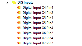
DIG Inputs
| The data for the digital inputs can be found under DIG Inputs. X4 Pin4 -> socket 4, pin 4 .... |
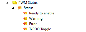
PWM Status
| The data for the PWM output can be found under PWM Status |
DEV Inputs
| The diagnostic data for the two voltages Us and Up can be found under DEV Inputs. TRUE = voltage <= approx. 18 VDC .... |

TACHO Output Channel 1
| The control data for the tacho input can be found under TACHO Output Channel 1. Reset Error - error reset |

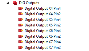
DO Outputs
| The data for the digital outputs can be found under DO Outputs. X5 pin4 -> socket 5, pin 4 .... |
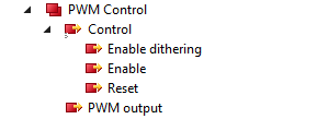
PWM control (activated through PDO assignment 0x1602, default PWM, alternatively AO)
| The control data for the PWM output can be found under PWM Control. Enable Dithering -> activate dithering Enable -> activate PWM output Reset -> reset on error PWM output -> load-independent current, depending on module rating (e.g. 1.2 A and setting in object 0x8050:10) |
AO outputs (activated through PDO assignment 0x1603), not activated by default
| The values for the analog output can be found under AO Outputs. Analog Output - output value |