Basic principles: "Positioning interface"
Predefined PDO Assignment
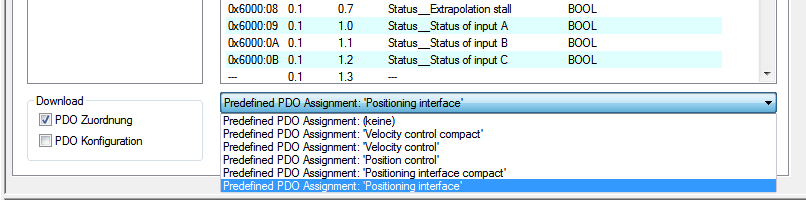
The "Predefined PDO Assignment" enables a simplified selection of the process data. Select the function “Positioning interface” or “Positioning interface compact” in the lower part of the Process data tab. As a result, all necessary PDOs are automatically activated and the unnecessary PDOs are deactivated.
Parameter set
Two objects are at the user’s disposal in the CoE for the configuration – the “POS Settings” (Index 8020) and the “POS Features” (Index 8021).
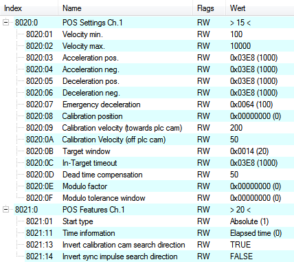
POS Settings
Velocity min.:
For reasons of performance when ramping down to the target position, EP7047-1032 needs a safety margin of 0.5%. That means that, depending on the maximum velocity reached and the configured deceleration, the time is calculated at which the deceleration ramp begins. In order to always reach the destination reliably, 0.5% is subtracted from the position determined. If the deceleration ramp has ended and the destination has not yet been reached, EP7047-1032 drives at the velocity “Velocity min.” to the destination. It must be configured in such a way that the motor is able to stop abruptly and without a step loss at this velocity.
Velocity max.:
The maximum velocity with which the motor drives during a travel command.
 | "Speed range" (index 8012:05) Velocity min./max. are standardised to the configured "Speed range" (Index 8012:05). This means that for a "Speed range" of 4000 full steps/second, for example, for a speed output of 100% (i.e. 4000 full steps/second) 10,000 should be entered under "Velocity max.", and 5,000 for 50% (i.e. 2000 full steps/second). |
Acceleration pos.:
Acceleration time in the positive direction of rotation.
The 5 parameters for acceleration also refer to the set “Speed range” and are given in ms. With a setting of 1000, EP7047-1032 accelerates the motor from 0 to 100% in 1000 ms. At a speed of 50% the acceleration time is linearly reduced to half accordingly.
Acceleration neg.:
Acceleration time in the negative direction of rotation.
Deceleration pos.:
Deceleration time in the positive direction of rotation.
Deceleration neg.:
Deceleration time in the negative direction of rotation.
Emergency deceleration:
Emergency deceleration time (both directions of rotation). If “Emergency stop” is set in the appropriate PDO, the motor is stopped within this time.
Calibration position:
The current counter value is loaded with this value after calibration.
Calibration velocity (towards plc cam):
Velocity with which the motor travels towards the cam during calibration.
Calibration velocity (off plc cam):
Velocity with which the motor travels away from the cam during calibration.
Target window:
Target window of the travel distance control. “In-Target” is set if the motor comes to a stop within this target window.
In-Target timeout:
“In-Target” is not set if the motor is not within the target window after the expiry of the travel distance control after this set time. This condition can be recognised only by checking the falling edge of “Busy”.
Dead time compensation:
Compensation of the internal propagation delays. This parameter does not have to be changed with standard applications.
Modulo factor:
The “Modulo factor” is referred to for the calculation of the target position and the direction of rotation in the modulo operating modes. It refers to the controlled system.
Modulo tolerance window:
Tolerance window for the determination of the start condition of the modulo operating modes.
POS Features
Start type:
The “Start type” specifies the type of calculation used to determine the target position (see below).
Time information:
The meaning of the “Actual drive time” displayed is configured by this parameter. At present this value cannot be changed, since there are no further selection options. The elapsed time of the travel command is displayed.
Invert calibration cam search direction:
In relation to a positive direction of rotation, the direction of the search for the calibration cam is configured here (travel towards the cam).
Invert sync impulse search direction:
In relation to a positive direction of rotation, the direction of the search is configured here in accordance with the HW sync pulse (travel away from the cam).
Information and diagnostic data
Information and diagnostic data
Via the information and diagnostic data, the user can obtain a more exact statement about which error occurred during a travel command.
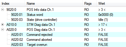
POS Info data
Status word:
The “Status word” reflects the status bits used in Index A020 in a data word, in order to be able to process them more simply in the PLC. The positions of the bits correspond to the number of the subindex-1.
Bit 0: Command rejected
Bit 1: Command aborded
Bit 2: Target overrun
State (drive controller):
The current status of the internal state machine is displayed here (see below).
POS Diag data:
Command rejected:
A dynamic change of the target position is not accepted each time by EP7047-1032, since this is then not possible. The new command is rejected in this case and indicated by the setting of this bit.
These 3 diagnostic bits are transmitted synchronously to the controller by setting “Warning” in the PDO.
Command aborted:
If the current travel command is prematurely aborted due to an internal error or by an “Emergency stop”.
Target overrun:
In the case of a dynamic change of the target position, the change may take place at a relatively late point in time. The consequence of this may be that a change in the direction of rotation is necessary and that the new target position may be overrun. “Target overrun” is set if this occurs.
States of the internal state machine
States of the internal state machine
The state (drive controller) (Index 9020:03) provides information about the current state of the internal state machine. For diagnostic purposes this can be read out by the PLC for the propagation delay. The internal cycle works constantly with 250 µs. A connected PLC cycle is very probably slower (e.g. 1 ms). For this reason it may be the case that some states are not visible at all in the PLC, since these will sometimes run through only one internal cycle.
|
Name |
ID |
Description |
|---|---|---|
|
INIT |
0x0000 |
Initialisation/preparation for the next travel command |
|
IDLE |
0x0001 |
Wait for the next travel command |
|
START |
0x0010 |
The new command is evaluated and the corresponding calculations are performed |
|
ACCEL |
0x0011 |
Acceleration phase |
|
CONST |
0x0012 |
Constant phase |
|
DECEL |
0x0013 |
Deceleration phase |
|
EMCY |
0x0020 |
An “Emergency stop” has been triggered |
|
STOP |
0x0021 |
The motor has stopped |
|
CALI_START |
0x0100 |
Start of a calibration command |
|
CALI_GO_CAM |
0x0110 |
The motor is being driven towards the cam |
|
CALI_ON_CAM |
0x0111 |
The cam has been reached |
|
CALI_GO_SYNC |
0x0120 |
The motor is being driven in the direction of the HW sync pulse |
|
CALI_LEAVE_CAM |
0x0121 |
The motor is being driven away from the cam |
|
CALI_STOP |
0x0130 |
End of the calibration phase |
|
CALIBRATED |
0x0140 |
The motor is calibrated |
|
NOT_CALIBRATED |
0x0141 |
The motor is not calibrated |
|
PRE_TARGET |
0x1000 |
The set position has been reached; the position controller “pulls” the motor further into the target; “In-Target timeout” is started here |
|
TARGET |
0x1001 |
The motor has reached the target window within the timeout |
|
TARGET_RESTART |
0x1002 |
A dynamic change of the target position is processed here |
|
END |
0x2000 |
End of the positioning phase |
|
WARNING |
0x4000 |
A warning state occurred during the travel command; this is processed here |
|
ERROR |
0x8000 |
An error state occurred during the travel command; this is processed here |
|
UNDEFINED |
0xFFFF |
Undefined state (can occur, for example, if the driver stage has no control voltage) |
States of the internal state machine
Standard sequence of a travel command
Standard sequence of a travel command
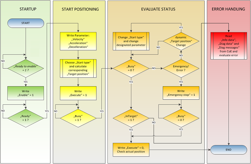
The “normally” sequence of a travel command is shown in the following flow diagram.
Coarse distinction is made between these four stages:
StartUp:
Test the system and the ready status of the motor.
Start positioning:
Write all variables and calculate the desired target position with the appropriate “Start type”. Subsequently, start the travel command.
Evaluate status:
Monitor the internal state of EP7047-1032 and, if necessary, dynamically change the target position.
Error handling:
In case of error, procure the necessary information from the CoE and evaluate it.
Start types
The “Positioning interface” offers different types of positioning. The following table contains all commands supported; these are divided into 4 groups.
Name | Command | Group | Description |
|---|---|---|---|
ABSOLUTE | 0x0001 | Absolute positioning to a specified target position | |
RELATIVE | 0x0002 | Relative positioning to a calculated target position; a specified position difference is added to the current position | |
ENDLESS_PLUS | 0x0003 | Endless travel in the positive direction of rotation (direct specification of a speed) | |
ENDLESS_MINUS | 0x0004 | Endless travel in the negative direction of rotation (direct specification of a speed) | |
ADDITIVE | 0x0006 | Additive positioning to a calculated target position; a specified position difference is added to the last target position | |
ABSOLUTE_CHANGE | 0x1001 | Dynamic change of the target position during a travel command to a new absolute position | |
RELATIVE_CHANGE | 0x1002 | Dynamic change of the target position during a travel command to a new relative position (the current changing position value is used here also) | |
ADDITIVE_CHANGE | 0x1006 | Dynamic change of the target position during a travel command to a new additive position (the last target position is used here) | |
MODULO_SHORT | 0x0105 | Modulo positioning along the shortest path to the modulo position (positive or negative), calculated by the “Modulo factor” (Index 8020:0E) | |
MODULO_SHORT_EXT | 0x0115 | Modulo positioning along the shortest path to the modulo position; the “Modulo tolerance window” (Index 8020:0F) is ignored | |
MODULO_PLUS | 0x0205 | Modulo positioning in the positive direction of rotation to the calculated modulo position | |
MODULO_PLUS_EXT | 0x0215 | Modulo positioning in the positive direction of rotation to the calculated modulo position; the "Modulo tolerance window" is ignored | |
MODULO_MINUS | 0x0305 | Modulo positioning in the negative direction of rotation to the calculated modulo position | |
MODULO_MINUS_EXT | 0x0315 | Modulo positioning in the negative direction of rotation to the calculated modulo position; the "Modulo tolerance window" is ignored | |
MODULO_CURRENT | 0x0405 | Modulo positioning in the last direction of rotation to the calculated modulo position | |
MODULO_CURRENT_EXT | 0x0415 | Modulo positioning in the last direction of rotation to the calculated modulo position; the "Modulo tolerance window" is ignored | |
CALI_PLC_CAM | 0x6000 | Start a calibration with cam (digital inputs) | |
CALI_HW_SYNC | 0x6100 | start a calibration with cam and HW sync pulse (C-track) | |
SET_CALIBRATION | 0x6E00 | Manually set the flag “Calibrated” | |
SET_CALIBRATION_AUTO | 0x6E01 | Automatically set the flag “Calibrated” on the first rising edge on “Enable” | |
CLEAR_CALIBRATION | 0x6F00 | Manually delete the calibration |
Supported "Start types" of the "Positioning interface"
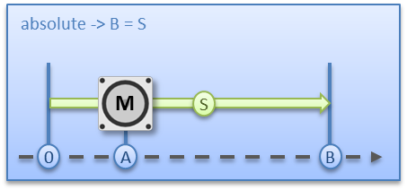
ABSOLUTE:
The absolute positioning represents the simplest positioning case. A position B is specified and travelled to from the start point A.
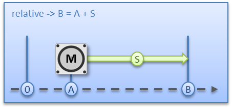
RELATIVE:
In relative positioning, the user specifies a position delta S, which is added to the current position A, producing the target position B.
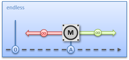
ENDLESS_PLUS / ENDLESS_MINUS:
The two start types “ENDLESS_PLUS” and “ENDLESS_MINUS” offer the possibility in the “Positioning interface” to specify a direct motor velocity in order to travel endlessly in the positive or negative direction with the specified accelerations.
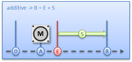
ADDITIVE:
For additive positioning, the position delta S specified by the user is added to the target position E used for the last travel command in order to calculate the target position B.
This kind of positioning resembles the relative positioning, but there is a difference. If the last travel command was completed successfully, the new target position is the same. If there was an error, however, be it that the motor entered a stall state or an “Emergency stop” was triggered, the current position is arbitrary and not foreseeable. The user now has the advantage that he can use the last target position for the calculation of the following target position.
ABSOLUTE_CHANGE / RELATIVE_CHANGE / ADDITIVE_CHANGE:
These three kinds of positioning are completely identical to those described above. The important difference thereby is that the user uses these commands during an active travel command in order to dynamically specify a new target position.
The same rules and conditions apply as to the “normal” start types. “ABSOLUTE_CHANGE” and “ADDITIVE_CHANGE” are unique in the calculation of the target position i.e. in absolute positioning an absolute position is specified and in additive positioning a position delta is added to the momentarily active target position.
The change by means of "RELATIVE_CHANGE" must be used with caution, since the current position of the motor is also used here as the start position. Due to propagation delays in the system, the position indicated in the PDO never corresponds to the actual position of the motor! Therefore a difference to the desired target position always results in the calculation of the transferred position delta.
| Time of the change of the target position A change of the target position cannot take place at an arbitrary point in time. If the calculation of the output parameters shows that the new target position cannot be readily reached, the command is rejected and the “Command rejected” bit is set. This is the case, for example, at standstill (since a standard positioning is expected here) and in the acceleration phase (since at this point the braking time cannot be calculated yet). |
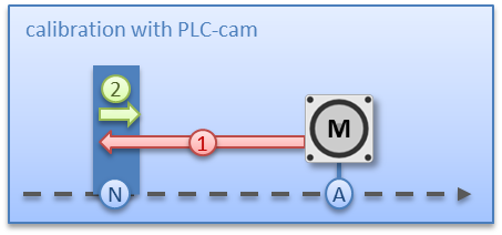
CALI_PLC_CAM / CALI_HW_SYNC / SET_CALIBRATION / SET_CALIBRATION_AUTO / CLEAR_CALIBRATION:
The simplest calibration case is calibration by cam only (connected to one digital input).
Here, the motor travels in the 1st step with velocity 1 (Index 0x8020:09) in direction 1 (Index 0x8021:13) towards the cam. Subsequently, in the 2nd step, it travels with velocity 2 (Index 0x8020:0A) in direction 2 (Index 8021:14) away from the cam. After the "In-Target timeout" (Index 8020:0C) has elapsed, the calibration position (Index 0x8020:08) is taken on as the current position.
With this simple calibration it must be noted that the position detection of the cam is only exact to a certain degree. The digital inputs are not interrupt-controlled and are “only” polled. The internal propagation delays may therefore result in a system-related position difference.
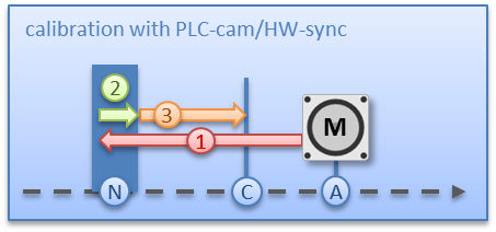
For a more precise calibration, an HW sync pulse (C-track) is used in addition to the cam. This calibration proceeds in exactly the same way as described above, up to the point at which the motor travels away from the cam. The travel is not stopped immediately; instead, the sync pulse is awaited. Subsequently, the “In-Target timeout” runs down again and the calibration position is taken on as the current position.
If calibration by hardware is not possible due to the circumstances of the application, the user can also set the “Calibrated” bit manually or automatically. The manual setting or deletion takes place with the commands “SET_CALIBRATION” and “CLEAR_CALIBRATION”.
It is simpler, however, if the standard start types (Index 0x8021:01) are set to “SET_CALIBRATION_AUTO”. The “Calibrated” bit will now be set automatically by the first rising edge on “Enable”. The command is conceived only for this purpose; therefore, it does not make sense to use it via the synchronous data exchange.
MODULO:
The modulo position of the axis is a piece of additional information about the absolute axis position. Modulo positioning represents the required target position in a different way. Contrary to the standard types of positioning, the modulo positioning has several pitfalls, since the desired target position can be interpreted differently.
The modulo positioning refers in principle to the "Modulo factor" (Index 0x8020:0E), which can be set in the CoE. In the following examples, a rotary axis with a “Modulo factor” equivalent to 360 degrees is assumed.
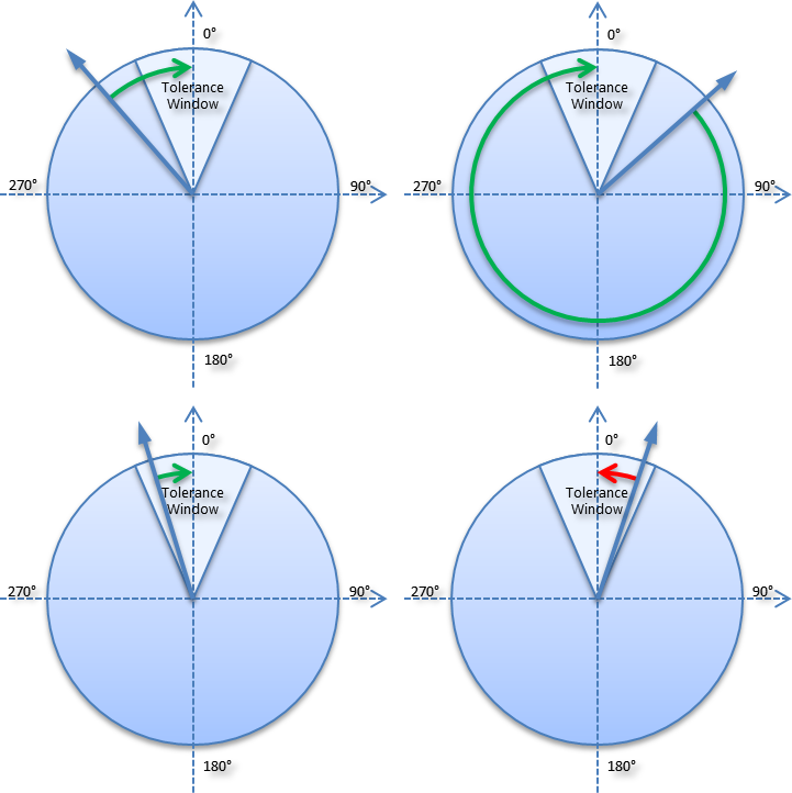
The “Modulo tolerance window” (Index 0x8020:0F) defines a position window around the current modulo target position of the axis. The window width is twice the specified value (set position ± tolerance value). A detailed description of the tolerance window is provided below.
The positioning of an axis is always referenced to its current actual position. The actual position of an axis is normally the target position of the last travel command. Under certain circumstances (incorrect positioning due to the axis stalling, or a very coarse resolution of the connected encoder), however, a position not expected by the user may arise. If this possibility is not considered, subsequent positioning may lead to unexpected behaviour.
Example:
An axis is positioned to 0°, with the result that subsequently the actual position of the axis is exactly 0°. A further modulo travel command to 360° in positive direction results in a full turn, with the subsequent modulo position of the axis of once again being exactly 0°. If the axis comes to a stop somewhat in front of or behind the target position for mechanical reasons, the next travel command does not behave as one would expect. If the actual position lies slightly below 0° (see fig. 9, below left), a new travel command to 0° in the positive direction leads only to a minimal movement. The deviation that arose beforehand is compensated and the position is subsequently exactly 0° once more. If the position lies slightly above 0°, however, the same travel command leads to a full revolution in order to reach the exact position of 0° again. This problem occurs if complete turns by 360° or multiples of 360° were initiated. For positioning to an angle that is significantly different from the current modulo position, the travel command is unambiguous.
In order to solve the problem, a “Modulo tolerance window” (Index 0x8020:0F) can be parameterized. This ensures that small deviations from the position that are within the window do not lead to different axis behavior. If, for example, a window of 1° is parameterized, in the case described above the axis will behave identically, as long the actual position is between 359° and 1°. If the position exceeds 0° by less than 1°, the axis is re-positioned in positive direction at a modulo start. In both cases, a target position of 0° therefore leads to minimum movement to exactly 0°. A target position of 360° leads to a full turn in both cases.
For values that are within the window range, the modulo tolerance window can therefore lead to movements against the specified direction. For small windows this is usually not a problem, because system deviations between set and actual position are compensated in both directions. This means that the tolerance window may also be used for axes that may only be moved in one direction due to their construction.
Modulo positioning by less than one turn
Modulo positioning from a starting position to a non-identical target position is unambiguous and requires no special consideration. A modulo target position in the range [0 ≤; position < 360] reaches the required target in less than one whole turn. No motion occurs if target position and starting position are identical. Target positions of more than 360 ° lead to one or more full turns before the axis travels to the required target position.
For a movement from 270° to 0°, a modulo target position of 0° (not 360°) should therefore be specified, because 360° is outside the basic range and would lead to an additional turn.
The modulo positioning distinguishes between three direction specifications: positive direction, negative direction and along the shortest path (MODULO_PLUS, MODULO_MINUS, MODULO_SHORT). For positioning along the shortest path, target positions of more than 360° are not sensible, because the movement towards the target is always direct. In contrast to positive or negative direction, it is therefore not possible to carry out several turns before the axis moves to the target.
For modulo positioning with start type "MODULO_SHORT", only modulo target positions within the basic period (e.g. less than 360°) are permitted, otherwise an error is returned.
| Positioning without the modulo tolerance window The Modulo tolerance window” (Index 0x8020:0F) is always taken into account in the “normal” types of modulo positioning. However, this is less desirable in some situations. In order to eliminate this "disadvantage", the comparable start types "MODULO_SHORT_EXT", "MODULO_PLUS_EXT", "MODULO_MINUS_EXT" and "MODULO_CURRENT_EXT" can be used, which ignore the modulo tolerance window. |
The following table shows some positioning examples:
Modulo start type | Absolute start position | Modulo target position | Relative travel path | Absolute end position | Modulo end position |
|---|---|---|---|---|---|
MODULO_PLUS | 90° | 0° | 270° | 360° | 0° |
MODULO_PLUS | 90° | 360° | 630° | 720° | 0° |
MODULO_PLUS | 90° | 720° | 990° | 1080° | 0° |
MODULO_MINUS | 90° | 0° | -90° | 0° | 0° |
MODULO_MINUS | 90° | 360° | -450° | -360° | 0° |
MODULO_MINUS | 90° | 720° | -810° | -720° | 0° |
MODULO_SHORT | 90° | 0° | -90° | 0° | 0° |
Examples of modulo positioning with less than one revolution
Modulo positioning with full turns
In principle, modulo positioning by one or full turns are no different than positioning to an angle that differs from the starting position. No motion occurs if target position and starting position are identical. For a full turn, 360° has to be added to the starting position. The behaviour described in the example shows that special attention must be paid to positionings with whole revolutions. The following table shows positioning examples for a starting position of approximately 90°. The modulo tolerance window is set to 1° here. Special cases for which the starting position is outside this window are identified.
|
Modulo start type |
Absolute start position |
Modulo target position |
Relative travel path |
Absolute end position |
Modulo end position |
Note |
|---|---|---|---|---|---|---|
|
MODULO_PLUS |
90.00° |
90.00° |
0.00° |
90.00° |
90.00° |
|
|
MODULO_PLUS |
90.90° |
90.00° |
-0.90° |
90.00° |
90.00° |
|
|
MODULO_PLUS |
91.10° |
90.00° |
358.90° |
450.00° |
90.00° |
outside TF |
|
MODULO_PLUS |
89.10° |
90.00° |
0.90° |
90.00° |
90.00° |
|
|
MODULO_PLUS |
88.90° |
90.00° |
1.10° |
90.00° |
90.00° |
outside TF |
|
MODULO_PLUS |
90.00° |
450.00 |
360.00° |
450.00° |
90.00° |
|
|
MODULO_PLUS |
90.90° |
450.00° |
359.10° |
450.00° |
90.00° |
|
|
MODULO_PLUS |
91.10° |
450.00° |
718.90° |
810.00° |
90.00° |
outside TF |
|
MODULO_PLUS |
89.10° |
450.00° |
360.90° |
450.00° |
90.00° |
|
|
MODULO_PLUS |
88.90° |
450.00° |
361.10° |
450.00° |
90.00° |
outside TF |
|
MODULO_PLUS |
90.00° |
810.00 |
720.00° |
810.00° |
90.00° |
|
|
MODULO_PLUS |
90.90° |
810.00 |
719.10° |
810.00° |
90.00° |
|
|
MODULO_PLUS |
91.10° |
810.00 |
1078.90° |
1170.00° |
90.00° |
outside TF |
|
MODULO_PLUS |
89.10° |
810.00 |
720.90° |
810.00° |
90.00° |
|
|
MODULO_PLUS |
88.90° |
810.00 |
721.10° |
810.00° |
90.00° |
outside TF |
|
MODULO_MINUS |
90.00° |
90.00° |
0.00° |
90.00° |
90.00° |
|
|
MODULO_MINUS |
90.90° |
90.00° |
-0.90° |
90.00° |
90.00° |
|
|
MODULO_MINUS |
91.10° |
90.00° |
-1.10° |
90.00° |
90.00° |
outside TF |
|
MODULO_MINUS |
89.10° |
90.00° |
0.90° |
90.00° |
90.00° |
|
|
MODULO_MINUS |
88.90° |
90.00° |
-358.90° |
-270.00° |
90.00° |
outside TF |
|
MODULO_MINUS |
90.00° |
450.00° |
-360.00° |
-270.00° |
90.00° |
|
|
MODULO_MINUS |
90.90° |
450.00° |
-360.90° |
-270.00° |
90.00° |
|
|
MODULO_MINUS |
91.10° |
450.00° |
-361.10° |
-270.00° |
90.00° |
outside TF |
|
MODULO_MINUS |
89.10° |
450.00° |
-359.10° |
-270.00° |
90.00° |
|
|
MODULO_MINUS |
88.90° |
450.00° |
-718.90° |
-630.00° |
90.00° |
outside TF |
|
MODULO_MINUS |
90.00° |
810.00° |
-720.00° |
-630.00° |
90.00° |
|
|
MODULO_MINUS |
90.90° |
810.00° |
-720.90° |
-630.00° |
90.00° |
|
|
MODULO_MINUS |
91.10° |
810.00° |
-721.10° |
-630.00° |
90.00° |
outside TF |
|
MODULO_MINUS |
89.10° |
810.00° |
-719.10° |
-630.00° |
90.00° |
|
|
MODULO_MINUS |
88.90° |
810.00° |
-1078.90° |
-990.00° |
90.00° |
outside TF |
Examples of modulo positioning with whole revolutions
Examples of two travel commands with a dynamic change of the target position
Without overrun of the target position
|
Time |
POS Outputs |
POS Inputs |
Description |
|---|---|---|---|
|
t1: |
Execute = 1 |
Busy = 1 |
- Specification of the first parameter |
|
t2: |
|
Accelerate = 0 |
- End of the acceleration phase |
|
t3: |
Target position = 100000 |
|
- Change of the parameters |
|
t4: |
|
Decelerate = 1 |
- Start of the deceleration phase |
|
t5: |
Execute = 0 |
Busy = 0 |
- End of the deceleration phase |
|
t6 - t9: |
|
|
- Absolute travel back to the start position 0 |
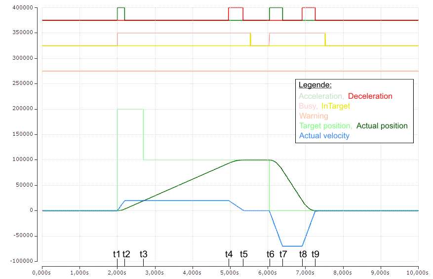
(The axis scaling refers only to the positions, not to the speed or the status bits)
With overrun of the target position
|
Time |
POS Outputs |
POS Inputs |
Description |
|---|---|---|---|
|
t1: |
Execute = 1 |
Busy = 1 |
- Specification of the 1st parameter |
|
t2: |
|
Accelerate = 0 |
- End of the 1st acceleration phase |
|
t3: |
Target position = 100000 |
Warning = 1 |
- Change of the parameters |
|
t4: |
|
Accelerate = 1 |
- End of the 1st deceleration phase |
|
t5: |
|
Accelerate = 0 |
- End of the 2nd acceleration phase |
|
t6: |
Execute = 0 |
Busy = 0 |
- End of the 2nd deceleration phase |
|
t7 - t10: |
|
|
- Absolute travel back to the start position 0 |
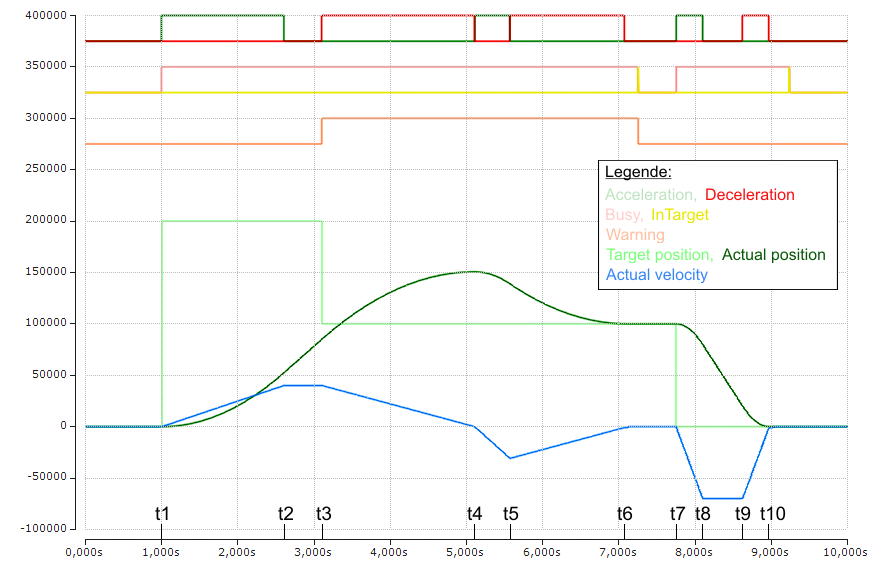
(The axis scaling refers only to the positions, not to the speed or the status bits)