Profile specific objects (0x6000-0xFFFF)
Index 90n0 IO Info data Ch.[1, 2, 3, …]
- Index 9000 IO Info data Ch.1
- Index 9010 IO Info data Ch.2
- Index 9020 IO Info data Ch.3
- …
Index (hex) | Name | Meaning | Data type | Flags | Default |
|---|---|---|---|---|---|
90n0:0 | IO Info data | Max. Subindex | UINT8 | RO | 0x27 (39dec) |
90n0:04 | Device ID | The device ID is used for validating the IO-Link device. | UINT32 | RO | 0x00000000 (0dec) |
90n0:05 | VendorID | The vendor ID is used for validating the manufacturer of the IO-Link device. | UINT32 | RO | 0x00000000 (0dec) |
90n0:07 | IO-Link revision | ID of the specification version based on which the IO-Link device communicates. Bit 0-3: MinorRev | UINT8 | RO | 0x00 (0dec) |
90n0:20 | FrameCapability | The Frame Capability indicates certain functionalities of the IO-Link device (e.g. SPDU supported). Bit 0: SPDU | UINT8 | RO | 0x00 (0dec) |
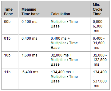
90n0:21 | Min cycle time | The cycle time refers to the communication between the IO-Link master and the IO-Link device. Bit 6 and 7: Time Base
| UINT8 | RO | 0x00 (0dec) |
Index (hex) | Name | Meaning | Data type | Flags | Default |
|---|---|---|---|---|---|
90n0:22 | Offset time | reserved | UINT8 | RO | 0x00 (0dec) |
90n0:23 | Process data in length | These parameters are transferred in the IO-Link format for "Process data in length". Bit 7: Bit 6: Bit 0 to 4: | UINT8 | RO | 0x00 (0dec) |
90n0:24 | Process data out length | These parameters are transferred in the IO-Link format for "Process data out length". Bit 7: Bit 6: Bit 0 to 4: | UINT8 | RO | 0x00 (0dec) |
90n0:26 | Reserved | reserved | UINT16 | RO | 0x0000 (0dec) |
90n0:27 | Reserved2 | reserved | UINT16 | RO | 0x0000 (0dec) |
Index A0n0 IO Diag data Ch.[1, 2, 3, …]
- Index A000 IO Diag data Ch.1
- Index A010 IO Diag data Ch.2
- Index A020 IO Diag data Ch.3
- …
Index (hex) | Name | Meaning | Data type | Flags | Default |
|---|---|---|---|---|---|
A0n0:0 | IO Diag data Ch.[1, 2, 3, …] | Max. Subindex | UINT8 | RO | 0x02 (2dec) |
A0n00:01 | IO-Link State | The value of the IO-Link state corresponds to a state from the IO-Link master state machine 0: INACTIVE 7: PREOPERATE | UINT8 | RO | 0x00 (0dec) |
A0n00:02 | Lost Frames | This parameter counts the number of lost IO-Link telegrams. This value is deleted whenever IO-Link starts up, otherwise it is incremented continuously. | UINT8 | RO | 0x00 (0dec) |
Index F000 Modular device profile
Index (hex) | Name | Meaning | Data type | Flags | Default |
|---|---|---|---|---|---|
F000:0 | Modular device profile | General information about the Modular Device Profile | UINT8 | RO | 0x02 (2dez) |
F000:01 | Module index distance | Index distance between the objects of two channels | UINT16 | RO | 0x0010 (16dez) |
F000:02 | Maximum number of modules | Number of channels | UINT16 | RO | 0x0004 (4dez) |
Index F008 Code word
Index (hex) | Name | Meaning | Data type | Flags | Default |
|---|---|---|---|---|---|
F008:0 | Code word | reserved | UINT32 | RW | 0x00000000 (0dez) |
Index F010 Module list
Index (hex) | Name | Meaning | Data type | Flags | Default |
|---|---|---|---|---|---|
F010:0 | Module list | Max. Subindex | UINT8 | RW | 0x04 (4dez) |
F010:01 | SubIndex 001 | - | UINT32 | RW | 0x0000184C (6220dez) |
F010:02 | SubIndex 002 | - | UINT32 | RW | 0x0000184C (6220dez) |
F010:03 | SubIndex 003 | - | UINT32 | RW | 0x0000184C (6220dez) |
F010:04 | SubIndex 004 | - | UINT32 | RW | 0x0000184C (6220dez) |
Index F100 Diagnosis Status data
See chapter Status of the IO-Link ports.
Index (hex) | Name | Meaning | Data type | Flags | Default |
|---|---|---|---|---|---|
F100:0 | Diagnosis Status data | Max. Subindex | UINT8 | RO | 0x04 (4dec) |
F100:01 | State Ch1 | Status byte Ch. 1 | UINT8 | RO | 0x00 (0dec) |
F100:02 | State Ch2 | Status byte Ch. 2 | UINT8 | RO | 0x00 (0dec) |
F100:03 | State Ch3 | Status byte Ch. 3 | UINT8 | RO | 0x00 (0dec) |
… | … | … | … | … | … |
Index F900 Info data
Index (hex) | Name | Meaning | Data type | Flags | Default |
|---|---|---|---|---|---|
F900:0 | Info data | Max. Subindex | UINT8 | RO | 0x09 (9dez) |
F900:01 | IO-Link Version | - | UINT8 | RO | 0x10 (16dez) |