Objects for commissioning
Index 1011 Restore default parameters
Index (hex) | Name | Meaning | Data type | Flags | Default |
|---|---|---|---|---|---|
1011:0 | Restore default parameters | Restore default parameters | UINT8 | RO | 0x01 (1dec) |
1011:01 | SubIndex 001 | If this object is set to "0x64616F6C" in the set value dialog, all backup objects are reset to their delivery state. | UINT32 | RW | 0x00000000 (0dec) |
Index 80n0 IO Settings Ch.[1, 2, 3, …]
- Index 8000 IO Settings Ch.1
- Index 8010 IO Settings Ch.2
- Index 8020 IO Settings Ch.3
- …
 | Recommendation: Configuration via configuration tool TwinCAT includes a graphical configuration tool for IO-Link masters and IO-Link devices. With this tool the configuration is easier and clearer than via the CoE parameters. See chapter Configuration of the IO link master. |
Index (hex) | Name | Meaning | Data type | Flags | Default |
|---|---|---|---|---|---|
80n0:0 | IO Settings | IO Settings Ch.[1 … 8] | UINT8 | RW | 0x28 (40dec) |
80n0:04 | Device ID | The Device ID is used for validating the IO-Link device. | UINT32 | RW | 0x00000000 (0dec) |
80n0:05 | Vendor ID | The Vendor ID is used for validating the vendor of the IO-Link device. | UINT32 | RW | 0x00000000 (0dec) |
80n0:20 | IO-Link Revision | The version of the IO-Link specification according to which the IO-Link device communicates. Bit 0-3: MinorRev | UNIT8 | RW | 0x00 (0dec) |
80n0:21 | Frame capability | The Frame capability indicates certain functionalities of the IO-Link device (e.g. SPDU supported). Bit 0: SPDU | UINT8 | RW | 0x00 (0dec) |
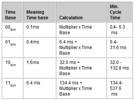
80n0:22 | Min cycle time | The cycle time refers to the communication between the IO-Link master and the IO-Link device. This value is transferred in the IO-Link format for Min Cycle Time. Bit 6 and 7: Time Base 0x00: The IO-Link master automatically uses the smallest possible update time of the IO-Link device.
| UINT8 | RW | 0x00 (0dec) |
Index (hex) | Name | Meaning | Data type | Flags | Default |
|---|---|---|---|---|---|
80n0:23 | Offset time | reserved | UINT8 | RW | 0x00 (0dec) |
80n0:24 | Process data in length | These parameters are transferred in the IO-Link format for "Process data in length". Bit 7: Bit 6: Bit 0 to 4: | UINT8 | RW | 0x00 (0dec) |
80n0:25 | Process data out length | These parameters are transferred in the IO-Link format for "Process data out length". Bit 7: Bit 6: Bit 0 to 4: | UINT8 | RW | 0x00 (0dec) |
80n0:26 | Compatible ID | reserved | UINT16 | RW | 0x0000 (0dec) |
80n0:27 | Reserved | reserved | UINT16 | RW | 0x0000 (0dec) |
80n0:28 | Master Control | Possible values:
| UINT16 | RW | 0x0000 (0dec) |