EPIxxxx, ERIxxxx - Setting of the IO-Link device parameters
This chapter explains how to read out and set the IO-Link device parameters.
The number and type of the objects shown on the “Parameters” tab vary according to the type of sensor.
The default settings as stored in the IODD can initially be seen.
To open the “Parameter” tab
- 1. Click the IO-Link master in the TwinCAT tree structure.
- 2. Click the “IO-Link” tab.
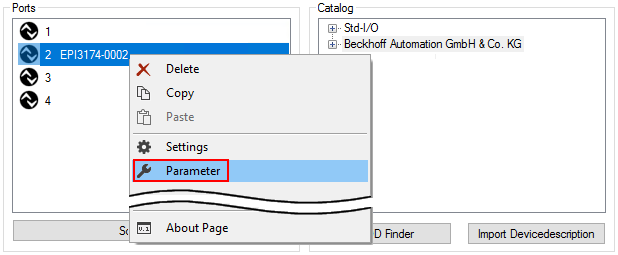
- 3. Select the port to which the IO-Link device is connected,
- 4. Double-click or by right-click to the port and select “Parameter”.
- The “Parameter” tab is opened.
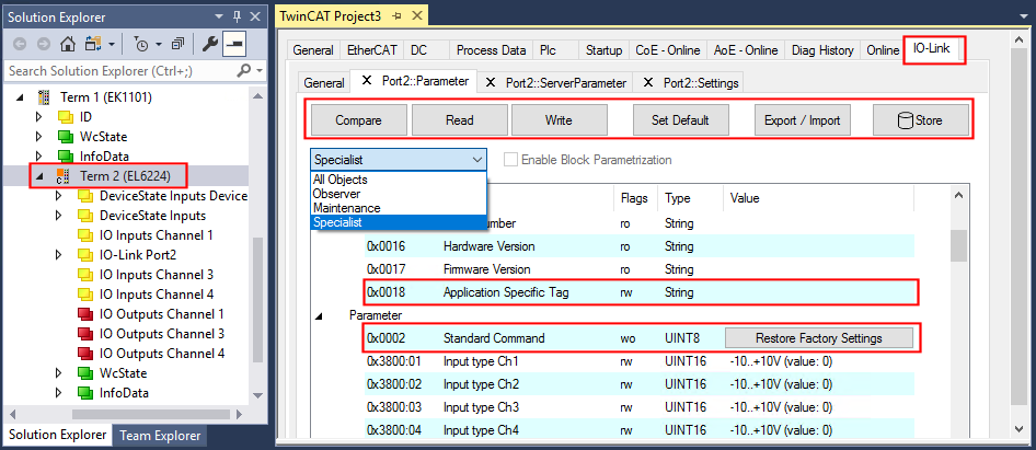
The device parameters are listed in the tab. The buttons Compare, Read, Write, Set Default, Export/Import and Store are located at the top of the tab. The “Read”, “Write” and “Store” buttons are used to read out the parameters stored in the IO-Link device, load them and store them in the parameter server of the master.
Different user roles can be selected from the drop-down menu. The default user role is “Specialist”. The parameters are displayed in different representations and scopes.
Restarting the IO link device or restoring of the application parameters is possible via the parameter Standard Command.
Application specific information can be specified in parameter (0x0018) Application Specific Tag.
“Compare” button
- 1. Press the “Compare” button.
- the parameter data of the configuration are compared with the parameter sets in the sensor.
- The result is displayed in the “Parameter” tab see following figures.
Conformity of configuration and sensor data
The match is confirmed by a green tick in front of the index. Matching values are displayed in the “Value” field (see index 0x0018 “Application Specific Tag”).
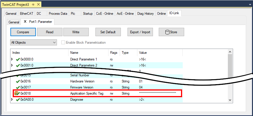 Fig.26: Display of matching data in the “Parameter” tab
Deviations between configuration and sensor data
Deviations are indicated by a pen-symbol in front of the index. If there are different values in the “Value” field, the value “Compare” is displayed (see Index 0x0018 “Application Specific Tag”).
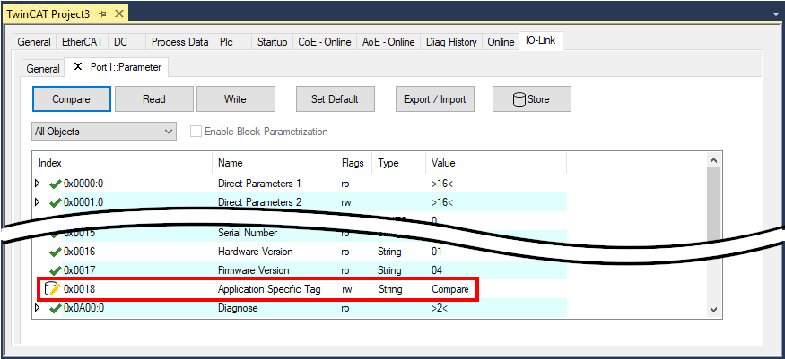 Fig.27: Display of deviating data in the “Parameter” tab
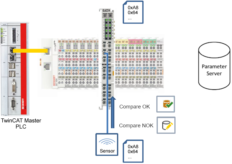 Fig.28: Compare configuration and sensor data
“Read” button
The default values from the IODD file are always preset
- 1. Press the “Read” button
- The current parameter values of the sensor are read. The successful reading of the data is confirmed with a green tick in front of the index.
“Write” button
The default values from the IODD file are always preset
- 1. Enter the desired value under “Value”.
- 2. Press the Enter key.
- The values are accepted.
- 3. Press the “Write” button.
- The data is written to the device (offline configuration is possible). The successful writing process is confirmed via a storing symbol in front of the index.
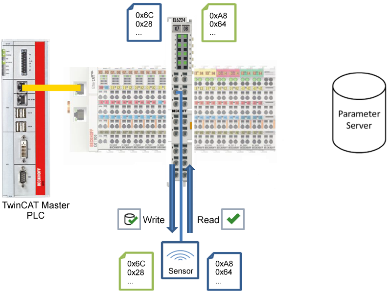 Fig.29: Write parameter data to the sensor, read parameter data from the sensor.
“Set Default” button
- 1. Press the “Set Default” button.
- All parameter values are set to the default settings.
 | Write default-values to the sensor Note that the default-values must also be written to the device via the “Write” button. |
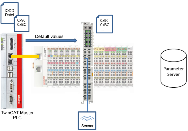 Fig.30: Reset parameter values to default
“Export / Import” button
The set parameter values can be exported as a .vbs file and restored later via Import.
- 1. Press the “Export / Import” button (see the diagram below (1)).
- The Import / Export dialog is opened
- 2. Specify the path under which you want to export or import the .vbs file, see fig. (2) below and confirm with the “Open” button, see fig. (4) below.
- 3. In addition, the export options “Attach Store Command” and “Enable Block Parametrization” can be selected as shown in fig. (3) below.
- “Attach Store Command”: The parameters are loaded into the parameter server after the script has written all values.
- “Enable Block Parametrization”: Block parameterization is enabled. For some sensors, writing is only possible when block parameterization is enabled.
- 4. Press the “Export” or “Import” button
- The parameters are adopted from the imported file. The change of parameters is marked with a pencil symbol.
- 5. Write the new parameter values to the sensor via “Write” button.
- The data is written to the device (offline configuration is possible). The successful writing process is confirmed via a storing symbol in front of the index.
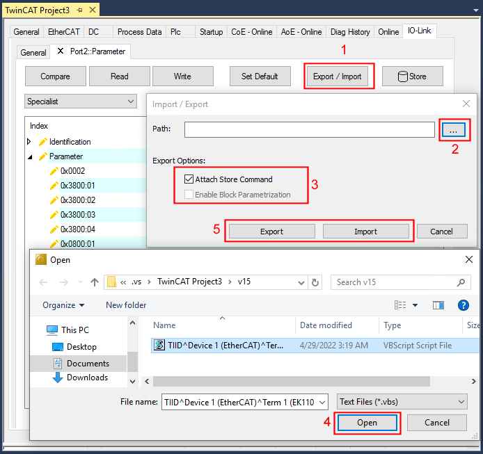 Fig.31: Parameterization IO-Link device - Export / Import
“Store” button
- 1. Click “Store” (data storage):
- The Beckhoff IO-Link master stores sensor-dependent-data, e. g. the following parameters
(0x0018) “Application-Specific Tag”,
(0x08n0) “Settings” and
0x3800 “Range Settings”.
The success of storing process is marked with the storing symbol. - If the IO-Link device is exchanged for a similar module, the device can be restored.
The stored values are displayed in the “ServerParameter” tab
- 1. Right-click on the device and select “Parameter Server” from the menu.
- The stored values are displayed.
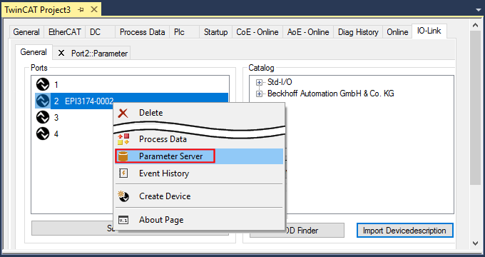 Fig.32: Open the “ServerParameter” tab
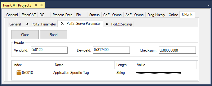 Fig.33: „ServerParameter“ tab
Activate store button via PLC
As for CoE, the Indexgroup of an ADS command is specified as 0xF302 for the IO link data channel.
According to the IO-Link specification devices with ISDU support shall use index 0x0002 to receive the SystemCommand. The following list displays coding examples for system commands (ISDU), the complete table “Coding of SystemCommand (ISDU)” can be found in the IO-Link specification.
Command | Command | Name of the command | Definition |
|---|---|---|---|
…. |
|
|
|
0x01 | 1 | ParamUploadStart | Start Parameter Upload |
0x02 | 2 | ParamUploadEnd | Stop Parameter Upload |
0x03 | 3 | ParamDownloadStart | Start Parameter Download |
0x04 | 4 | ParamDownloadEnd | Stop Parameter Download |
0x05 | 5 | ParamDownloadStore | Finalize parameterization and start Data Storage |
0x06 | 6 | ParamBreak | Cancel all Param commands |
…. |
|
|
|
Use an ADS Write function block for activating the store-function via the plc. The following figure shows a sample code for activation of the store-Button (command 0x05 “ParamDownloadStore”)
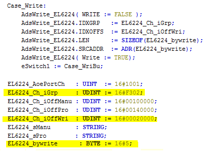 Fig.34: Sample code for activation of the store-function via the plc
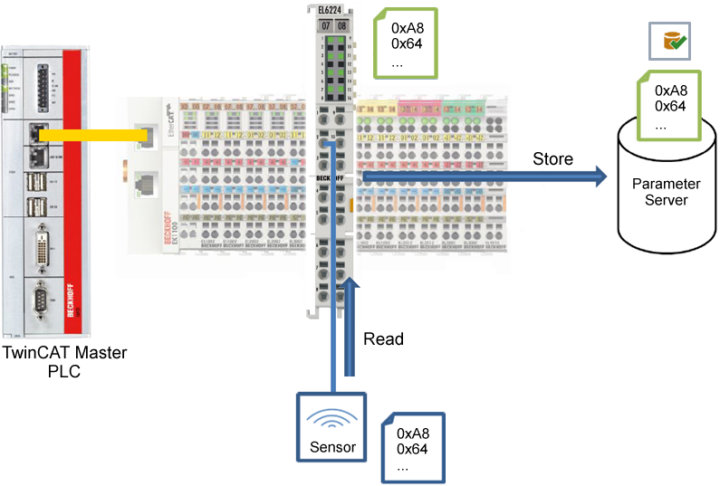 Fig.35: Store parameters
Standard Command (Index 0x0002)
The IO-Link master writes various IO-Link-specific commands to the “Standard Command” during startup. Some of these commands are available in the TwinCAT interface (see figure below).
- 1. Click “Standard Command” in the parameter list of the “All Objects” user role, then double-click “Standard Command” in the right-hand field.
- 2. Select the desired value from the list of different options and
- “Device Reset”: Restarts the IO-Link device.
- “Application Reset”: No function.
- “Restore Factory Settings”: Restoring the application parameters, i.e. the Settings parameter (0x0800).
- 3. Use the “Write” button (as described above).
- The data is written to the device (offline configuration is possible). The successful writing process is confirmed via a storing symbol in front of the index.
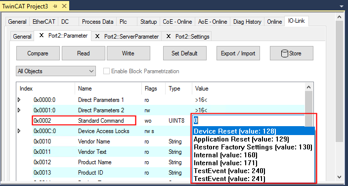 Fig.36: Parameters IO-Link device “Standard Command”
“Application Specific Tag” (Index 0x0018)
Application-specific information can be entered and stored here.
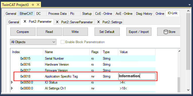 Fig.37: Parameters IO-Link device: “Application Specific Tag”