Process image
The following figure shows the representation of the process image in delivery state.
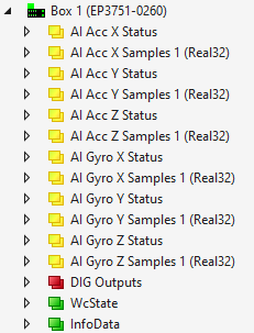
You can configure the process image via "Predefinded PDO Assignments", see chapter Setting a Predefined PDO Assignment.
The process data objects are described below as an example for the acceleration measuring axis "Acc X". The descriptions can be transferred to the other measuring axes "Acc Y/Z" and "Gyro X/Y/Z".
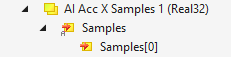
AI Acc X Samples 1 (Real32)
| Samples[0] |
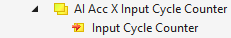
AI Acc X Input Cycle Counter (Real32)
This process data object is disabled in the factory settings. You can enable it by setting a corresponding Predefined PDO Assignment, see chapter Setting a Predefined PDO Assignment.
| Input Cycle Counter |
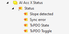
AI Acc X Status
| Slope detected |
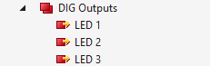
Dig Outputs
| LED 1, LED 2, LED 3 |