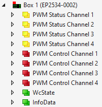
The process image contains the following process data objects in the delivery state:
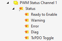
PWM Status Channel n
Ready to Enable All prerequisites for enabling the output are fulfilled. Enabling via the bit "Enable".
Warning Warning message. To narrow down the cause, see chapter Diagnostics.
Error Error message. As a result, the output was disabled. To narrow down the cause of the error, see chapter Diagnostics. Once the cause of the error has been eliminated, you can re-enable the output with the bit "Reset".
Diag Indicates that a new message is available in the Diag History.
TxPDO Toggle Is inverted each time the respective higher-level process data object "PWM Status Channel n" is updated.
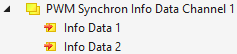
PWM Synchron Info Data Channel n
Info Data 1 Additional information, selectable via CoE parameter 8pp0:21 "Select Info Data 1". In the delivery state: "Actual Current", i.e. the measured output current.
Info Data 2 Additional information, selectable via CoE parameter 8pp0:22 "Select Info Data 2". In the delivery state: "Set Current", i.e. the output current setpoint.
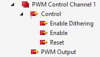
Enable Dithering Enables dithering, see chapter Dithering. Prerequisite: The CoE parameter 8pp0:03 "Enable Dithering" must be TRUE.
Enable Enables the output. No PWM output as long as this bit has the value 0. Precondition: The bit "Ready to Enable" has the value 1. Notice Configure the output before enabling, see chapter Basic configuration
Reset Acknowledges an error and re-enables the output.
PWM output Output setpoint. Value range: 0 to 32767 (data type INT)
In the "Current Control" operation mode, the value range corresponds to an output current of 0 to "Max Current" (parameter 80n0:10; default: 100 % corresponding to 2 A).
In operation mode "Voltage Control", the value range corresponds to a duty cycle of 0 … 100 % 1) or an output voltage of 0 to UP = 24 VDC.
1) The upper limit of the duty cycle is 97 %. If you set a higher value (i.e. higher than 31784), the box will still only output 97 %.