TC measurement with Beckhoff terminals
Thermocouple specification and conversion
Temperature measurement with thermocouples generally comprises three steps:
- Measuring the electrical voltage,
- optional: Temperature measurement of the internal cold junction,
- optional: Software-based conversion of the voltage into a temperature value according to the set thermocouple type (K, J, …).
All three steps can take place locally in the Beckhoff measuring device. Device-based transformation can be disabled if the conversion is to take place in the higher-level control system. Depending on the device type, several thermocouple conversions are available, which differ in terms of their software implementation.
For Beckhoff thermocouple measuring devices this means that
- a specification of the electrical voltage measurement is provided and
- based on this, the effect on temperature measurement is specified depending on the supported thermocouple type. Note that thermocouple characteristic curves are always realized as higher-order equations or by a sampling points table in the software, therefore a direct, linear U → T transfer only makes sense in a narrow range.
 | Data for the sensor types in the following table The values for the sensor types listed in the following table are shown here merely for informative purposes as an orientation aid. All data are given without guarantee and must be cross-checked against the data sheet for the respective sensor employed. |
The thermocouple measurement consists of a chain of measuring and computing elements that affect the attainable measurement deviation:
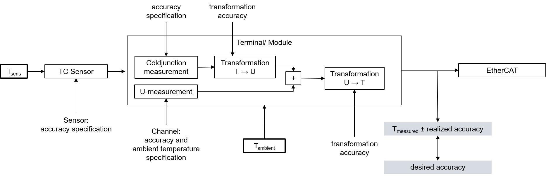 Fig.90: Concatenation of the uncertainties in temperature measurement with thermocouples
The given voltage specification is decisive for the achievable temperature measuring accuracy. It is applied to the possible thermocouple types in the following.
On account of
- the strong non-linearity that exists with thermocouple, which suggests a meaningful use of it in a limited temperature range (if possible),
- influence of the possibly used internal cold junction,
- the possible use of an external cold junction, the specification of which is not known at this point, and
- the influence of the ambient temperature on the evaluation unit used in the voltage and cold junction measurement (leads to a change in Tmeasured due to ∆Tambient)
detailed temperature specification tables are not given below, but rather
- one short table per thermocouple type
- with indication of the electrical measuring range used in the voltage measurement
- with indication of the entire technically usable measuring range supported by the device. This is also the linearization range of the temperature transformation, usually the application range of the respective thermocouple specified in the standards.
Note: the electrical measuring range is designed to cover the entire linearization range. The entire temperature measuring range can therefore be used - with indication of the measuring range recommended by Beckhoff for this type. It is a subset of the technically usable measuring range and covers the measuring range commonly used in industry in which a relatively low measurement uncertainty is still achieved.
Since thermocouples have a non-linear characteristic curve across the entire implemented linearization range as shown in the chapter on thermocouple principles, the specification of measurement uncertainty over this entire range as the so-called basic accuracy would be unrealistic and even misleading. A much smaller uncertainty is achieved in the temperature range commonly used in industry. Nevertheless, it is of course possible to use the device outside of the "recommended measuring range" (but within the "technically usable measuring range") - with the specified measurement uncertainty in the "recommended measuring range" at an ambient temperature of 23 °C and 55 °C, where the measurement uncertainty at 55 °C corresponds to the value for 23 °C ±32 °C.
Thus, the measurement uncertainty at other ambient temperatures in the recommended measuring range can be approximately interpolated or extrapolated. The values can also be taken from the specification plot.
Attention when determining the temperature coefficient (TC [K/Kamb]): the specified values do not necessarily have to be available for the same Tsens! To determine TC, read the measurement uncertainty values from the plot at Tsens and calculate TC. - the "Specification Plot": a comprehensive specification statement as a graphical representation of the measurement uncertainty for Tsens at the two aforementioned ambient temperatures and additionally 39 °C in the entire technically usable measuring range. The representation of the measurement uncertainty at 39 °C ambient temperatures (mean temperature between 23 °C and 55 °C) shows the non-linear influence of the temperature on the measurement uncertainty.
If accuracy values outside of the "recommended measuring range" are required, they can thus be read graphically here.
- some formulas to calculate further parameters (offset / gain / non-linearity / repeatability / noise) from the specification at the desired operation point if required.
Notes on the calculation of detailed specifications
If further specifications are of interest, they can or must be calculated from the values given in the voltage specification.
The sequence:
- General: The conversion is explained here only for one measuring point (a certain input signal); the steps simply have to be repeated in case of several measuring points (up to the entire measuring range).
- The determination of the entire temperature error at a measuring point results from two steps:
- Determination of the temperature error from the error of the voltage measurement,
- Determination of the error by the cold junction measurement at the temperature of the measuring point.
- Note: Due to the non-linearity of the thermocouples, it is not possible to easily add the temperature errors
- If the measured voltage is not known at the measured temperature measuring point, the measured value MW = UMeasuring point (TMeasuring point) must be determined with the help of an U→T table.
- The deviation is calculated at this voltage value:
- Via the total equation

- or a single value, e.g. ESingle = 15 ppmFSV
- the measurement uncertainty in [mV] must be calculated:
Evoltage(Umeasuring point) = ETotal(Umeasuring point) · FSV
or: Evoltage(Umeasuring point) = ESingle(Umeasuring point) · FSV
or (if already known) e.g.: Evoltage(Umeasuring point) = 0.003 mV - Also, for the calculation of the cold junction error required for further calculations, the entire error must be calculated using the above equation.
- The slope at the point used must then be determined:
ΔUproK(Tmeasuring point) = [U(Tmeasuring point + 1 °C) - U(Tmeasuring point )] / 1 °C
with the help of an U→T table - The cold junction error is given as a temperature in °C. The temperature error must then be converted into a voltage error in [mV] via the slope at the temperature measuring point:
ECJC, U(Tmeasuring point) = ECJC, T · ΔUproK(Tmeasuring point) - The combined error in [mV] must then be calculated using a square addition of the voltage error and the cold junction error:

- For calibrated thermocouples, the thermocouple error can also be included at this point in order to determine the combined error of the entire system in mV. For this purpose, all three error influences in [mV] (voltage, cold junction, thermocouple) must be added squarely.
- The temperature measurement uncertainty can be calculated via the voltage measurement uncertainty and the slope
ETemp(Umeasuring point) = (Evoltage+CJC(Tmeasuring point)) / (ΔUproK(Tmeasuring point))
The numerical values used in the following three examples are for illustration purposes. The specification values given in the technical data remain authoritative.
Sample 1:
Basic accuracy of an ELM3704 at 35 °C ambient, measurement of 400 °C with thermocouple type K, without noise and aging influences:
Tmeasuring point = 400 °C
MW = UType K, 400°C = 16.397 mV

= 100.196 ppmFSV
FVoltage(Umeasuring point) = 100.196 ppmFSV · 80 mV = 8.016 µV
ΔUperK(Tmeasuring point) = (U(401 °C) - U(400 °C)) / (1 °C) = 42.243 µV/°C
FCJC, T = tbd
FCJC, U(Tmeasuring point) = tbd °C · 42.243 µV/°C = tbd µV
FVoltage+CJC = tbd
FELM3704@35°C, type K, 400°C = (Fvoltage+CJC µV) / (42.243 µV/°C) ≈ tbd °C (means ±tbd °C)
Sample 2:
Consideration of the repeatability alone under the above conditions:
Tmeasuring point = 400 °C
MW=Umeasuring point (400 °C) = 16.397 mV
FSingle = 20 ppmFSV
FVoltage = 20 ppmFSV · 80 mV = 1.6 µV
ΔUperK(Tmeasuring point) = (U(401 °C) - U(400 °C)) / (1 °C) = 42.243 µV/°C
FCJC, single = tbd °C
FCJC, Single, U(Tmeasuring point) = tbd °C · 42.243 µV/°C = tbd µV
FVoltage+CJC = tbd
FTemp(Umeasuring point) = (Fvoltage+CJC µV) / (42.243 µV/°C) ≈ tbd °C (means ±tbd °C)
Sample 3:
Consideration of the RMS noise alone without filter under the above conditions:
Tmeasuring point = 400 °C
MW=Umeasuring point (400 °C) = 16.397 mV
FSingle = 37 ppmFSV
FVoltage = 37 ppmFSV · 80 mV = 2.96 µV
ΔUperK(Tmeasuring point) = (U(401 °C) - U(400 °C)) / (1 °C) = 42.243 µV/°C
FCJC, single = tbd °C
FCJC, Single, U(Tmeasuring point) = tbd °C · 42.243 µV/°C = tbd µV
FVoltage+CJC = tbd
FTemp(Umeasuring point) = (Fvoltage+CJC µV) / (42.243 µV/°C) ≈ tbd °C (means ±tbd °C)