RTD/Pt1000 measurement
RTD specification and conversion
Temperature measurement with a resistance-dependent RTD sensor generally consists of two steps:
- Electrical measurement of the resistance, if necessary in several ohmic measuring ranges
- Conversion (transformation) of the resistance into a temperature value by software means according to the set RTD type (Pt100, Pt1000…).
Both steps can take place locally in the Beckhoff measurement device. The transformation in the device can also be deactivated if it is to be calculated on a higher level in the control. Depending on the device type, several RTD conversions can be implemented which only differs in software. This means for Beckhoff RTD measurement devices that
- a specification table of the electrical resistance measurement is given
- and based on this, the effect for the temperature measurement is given below depending on the supported RTD type. Note that RTD characteristic curves are always realized as higher-order equations or by a sampling points table in the software, therefore a linear R→T transfer only makes sense in a narrow range.
Application on the ELM350x
The ELM350x supports the measurement of resistances up to 2 kΩ in 2/3/4‑wire measurement and the conversion of Pt1000 RTD sensors up to 2000 Ω / 266 °C.
Although the ELM350x does not support a sole resistance measurement (without conversion to temperature), a resistance specification is given here because the temperature measurement is based on it.
Note to 2/3/4-wire connection within R/RTD-operation
With 2‑wire measurement, the line resistance of the sensor supply lines influences the measured value. If a reduction of this systematic error component is desirable for 2‑wire measurements, the resistance of the supply line to the measuring resistance should be taken into account, in which case the resistance of the supply line has to be determined first.
Taking into account the uncertainty associated with this supply line resistance, it can then be included statically in the calculation, in the EL3751 via 0x8000:13 and in the ELM350x/ ELM370x via 0x80n0:13.
Any change in resistance of the supply line due to ageing, for example, is not taken into account automatically. Just the temperature dependency of copper lines with approx. 4000 ppm/K (corresponds to 0.4%/K!) is not insignificant during 24/7 operation.
A 3‑wire measurement enables the systematic component to be eliminated, assuming that the two supply lines are identical. With this type of measurement, the lead resistance of a supply line is measured continuously. The value determined in this way is then deducted twice from the measurement result, thereby eliminating the line resistance. Technically, this leads to a significantly more reliable measurement. However, taking into account the measurement uncertainty, the gain from the 3‑wire connection is less significant, since this assumption is subject to high uncertainty, in view of the fact that the individual line that was not measured may be damaged, or a varying resistance may have gone unnoticed.
Therefore, although technically the 3‑wire connection is a tried and tested approach, for measurements that are methodological assessed based on measurement uncertainty, we strongly recommend fully‑compensated 4‑wire connection.
With both 2‑wire and 3‑wire connection, the contact resistances of the terminal contacts influence the measuring process. The measuring accuracy can be further increased by a user‑side adjustment with the signal connection plugged in.
Notice | |
Measurement of small resistances Especially for measurements in the range < 10 Ω, the 4‑wire connection is absolutely necessary due to the relatively high supply and contact resistances. It should also be considered that with such low resistances the relative measurement error in relation to the full scale value (FSV) can become high ‑ for such measurements resistance measurement terminals with small measuring ranges such as EL3692 in 4‑wire measurement should be used if necessary. |
Corresponding considerations also lead to the common connection methods in bridge operation:
- Full bridge: 4‑wire connection without line compensation, 6‑wire connection with full line compensation
- Half bridge: 3‑wire connection without line compensation, 5‑wire connection with full line compensation
- Quarter bridge: 2‑wire connection without line compensation, 3‑wire connection with theoretical line compensation and 4‑wire connection with full line compensation
Resistance measurement 2 kΩ | 2/3-wire 1) | 4-wire | |
|---|---|---|---|
Operation mode | 3 V feed voltage fixed setting on +Uv | ||
Measuring range, nominal | 2 kΩ (corresponds to PT1000 +266°C) | ||
Measuring range, end value (FSV) | 2 kΩ | ||
Measuring range, technically usable | 0 … 2 kΩ | ||
PDO LSB (Extended Range) | Extended range is not supported for resistance measurement | ||
PDO LSB (Legacy Range only) | Resistance measurement not available as separate measuring range on ELM350x. | ||
Basic accuracy: Measuring deviation at 23°C, with averaging, incl. Offset, typ. 6) | < ±0.012 %FSV | < ±0.011 %FSV | |
Extended basic accuracy: Measuring deviation at 0…55°C, with averaging, incl. Offset, typ. 6) | < ±0.0365 %FSV | < ±0.0345 %FSV | |
Offset/Zero point deviation (at 23°C) | EOffset | < 40 ppmFSV | < 30 ppmFSV |
Gain/scale/amplification deviation (at 23°C) | EGain | < 90 ppm | < 80 ppm |
Non-linearity over the whole measuring range | ELin | < 65 ppmFSV | < 65 ppmFSV |
Repeatability (at 23°C) | ERep | < 10 ppmFSV | < 10 ppmFSV |
Temperature coefficient, typ. | TcGain | < 10 ppm/K | < 10 ppm/K |
TcOffset | < 4 ppmFSV/K | < 1.5 ppmFSV/K | |
Common-mode rejection ratio (without filter) 3) | tbd. | tbd. | |
Common-mode rejection ratio (with 50/60 Hz FIR filter) 3) 5) | tbd. | tbd. | |
Largest short-term deviation during a specified electrical interference test, typ. | tbd. %FSV
| tbd. %FSV
| |
Input impedance (internal resistance) | tbd. | tbd. | |
1) The offset specification does not apply to 2-wire operation, since the offset is increased on the device side. Therefore, a system-side offset adjustment is recommended, see "Note on 2-/3-/4-wire connection in R/RTD mode". The final targeting basic acuuracy within the 2-wire operation is mainingly dependent by the quality of this system-side offset adjustment.
3) Values related to a common mode interference between SGND and internal ground.
5) the 50/60 Hz filter setting must be selected via the settings in the CoE depending on the local mains frequency (50 or 60 Hz); the respective nominal mains frequency then applies as the measuring point for common mode rejection or crosstalk.
6) Calculated value according to the equation for estimating usability at the given ambient temperature point or estimating usability over the specified ambient temperature range in operation (Tambient) as stated in chapter "General information on measuring accuracy/measurement uncertainty". In real use, for example at a relatively constant ambient temperature Tambient, a lower (better) achievable uncertainty is attained. A specific calculation according to chapter "General information on measuring accuracy/measurement uncertainty" is recommended, especially if the instrument allows a wider ambient temperature range in operation than 0...55 °C.
ELM3502 (20 ksps)
Resistance measurement 2 kΩ | 2/3-wire | 4-wire | |
|---|---|---|---|
Noise (without filtering, at 23°C) | ENoise, PtP | < 220 ppmFSV | < 220 ppmFSV |
ENoise, RMS | < 37 ppmFSV | < 37 ppmFSV | |
Max. SNR | > 88.6 dB | > 88.6 dB | |
Noisedensity@1kHz | < 0.29 | < 0.29 | |
Noise (with 50/60 Hz FIR filter, at 23°C) 5) | ENoise, PtP | < 14 ppmFSV | < 14 ppmFSV |
ENoise, RMS | < 2.3 ppmFSV | < 2.3 ppmFSV | |
Max. SNR | > 112.8 dB | > 112.8 dB | |

ELM3504 (10 ksps)
Resistance measurement 2 kΩ | 2/3-wire | 4-wire | |
|---|---|---|---|
Noise (without filtering, at 23°C) | ENoise, PtP | < tbd. ppmFSV | < tbd. ppmFSV |
ENoise, RMS | < tbd. ppmFSV | < tbd. ppmFSV | |
Max. SNR | > tbd. dB | > tbd. dB | |
Noisedensity@1kHz | < tbd. | < tbd. | |
Noise (with 50/60 Hz FIR filter, at 23°C) 5) | ENoise, PtP | < tbd. ppmFSV | < tbd. ppmFSV |
ENoise, RMS | < tbd. ppmFSV | < tbd. ppmFSV | |
Max. SNR | > tbd. dB | > tbd. dB | |
5) the 50/60 Hz filter setting must be selected via the settings in the CoE depending on the local mains frequency (50 or 60 Hz); the respective nominal mains frequency then applies as the measuring point for common mode rejection or crosstalk.
RTD measuring range
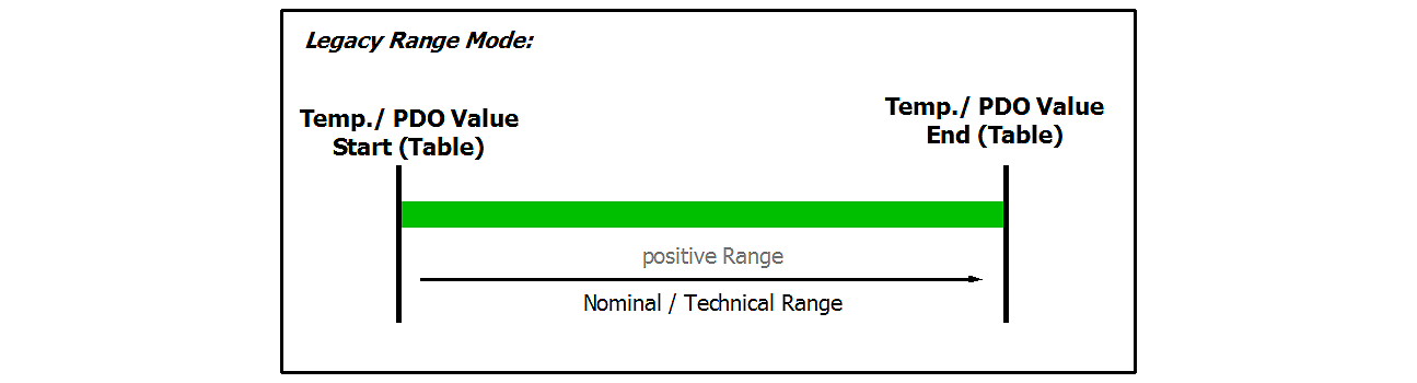 Fig.78: Chart: RTD measuring range
In temperature mode, only the legacy range is available, the extended range is not available.
The temperature display in [°C/digit] (e.g. 0.1°/digit or 0.01°/digit) is independent from the electrical measurement. It is “just” a display setting and results from the PDO setting, see chapter "Comissioning".
 | Data for the sensor types in the following table The values for the sensor types listed in the following table are shown here merely for informative purposes as an orientation aid. All data are given without guarantee and must be cross-checked against the data sheet for the respective sensor employed. |
The RTD measurement consists of a chain of measuring and computing elements that affect the attainable measurement deviation:
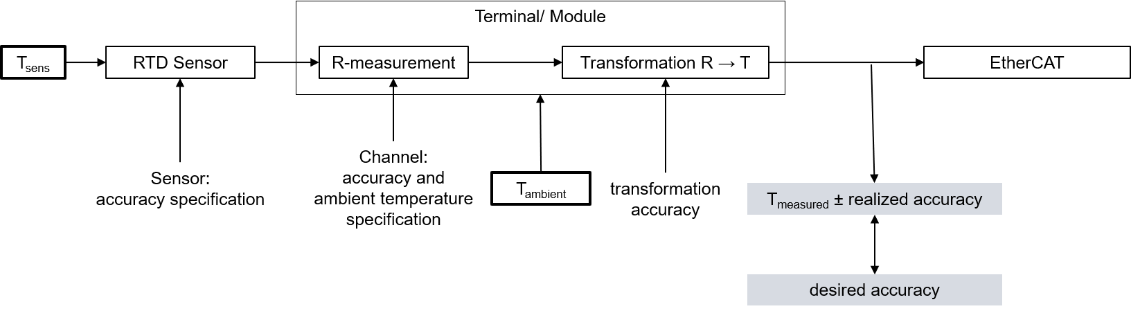 Fig.79: Concatenation of the uncertainties in RTD measurement
The given resistance specification is decisive for the attainable temperature measurement accuracy. It is applied to the possible RTD types in the following.
On account of
- the non-linearity existing in the RTD and thus the high dependency of the specification data on the sensor temperature Tsens and
- the influence of the ambient temperature on the analog input device employed (leads to a change in Tmeasured on account of ∆Tambient although Tsens = constant)
no detailed temperature specification table is given in the following, but
- a short table specifying the electrical measuring range and orientation value for the basic accuracy
- a graph of the basic accuracy over Tsens (this at two example ambient temperatures so that the attainable basic accuracy is implied on account of the actual existing ambient temperature)
- equations for calculating further parameters (offset/gain/non-linearity/repeatability/noise) if necessary from the resistance specification at the desired operating point
Supported RTD-types by the ELM350x:
- Pt1000 to DIN EN 60751/IEC751 with α= 0.0039083 [1/C°]
RTD temperature measurement | PT1000 2-wire | PT1000 3-wire | PT1000 4-wire |
|---|---|---|---|
Electrical measuring range used | 2 kΩ | ||
Starting value | -200°C ≈ 185.2 Ω | ||
End value | 266°C ≈ 2000 Ω | ||
PDO LSB (legacy range only) | 0.1/0.01/0.001°C/digit, depending on PDO setting | ||
Basic accuracy: measurement deviation at 23 °C terminal environment, with averaging, typ. | The achievable measurement uncertainty, as a system side offset, is essentially dependent on the line resistances and can at best reach the value of the 3-wire measurement. | < ±66 mK | < ±60 mK |
Temperature coefficient 2), typ. | < 3.3 mK/K | < 2.7 mK/K | |
2) The temperature coefficient, i.e. the change in the measured temperature value in relation to the change in the ambient temperature of the terminal, is not constant, as can be seen in the following plot. The value at a sensor temperature of 0 °C is given here as an orientation value. Further values can be taken from the plot.
Basic accuracy for PT1000, 3-wire connection:

Basic accuracy for PT1000, 4-wire connection:

If further specification data are of interest, they can or must be calculated from the values given in the resistance specification.
The sequence:
- General: The conversion is explained here only for one measuring point (a certain input signal); the steps simply must be repeated in case of several measuring points (up to the entire measuring range).
- If the measured resistance at the measured temperature measuring point is unknown, the measured value (MW) in [Ω] must be determined:
MW = RMeasuring point (TMeasuring point) with the help of an R→T table - The deviation at this resistance value is calculated
- Via the total equation

- or a single value, e.g. ESingle = 15 ppmFSV
- the measurement uncertainty in [Ω] must be calculated:
EResistance(RMeasuring point) = ETotal(RMeasuring point) ⋅ FSV
or: EResistance(RMeasuring point) = ESingle(RMeasuring point) ⋅ FSV
or (if already known) e.g.: EResistance(RMeasuring point) = 0.03 Ω - The slope at the point used must then be determined:
ΔRproK(TMeasuring point) = [ R(TMeasuring point + 1 °C) – R(TMeasuring point )] / 1 °C
with the help of an R→T table - The temperature measurement uncertainty can be calculated from the resistance measurement uncertainty and the slope
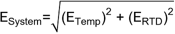
ETemp(RMeasuring point) = (EResistance(TMeasuring point)) / (ΔRproK(TMeasuring point) ) - To determine the error of the entire system consisting of RTD and the measuring device in [°C], the two errors must be added together quadratically:
The numerical values used in the following three examples are for illustration purposes. The specification values given in the technical data remain authoritative.
Example 1:
Basic accuracy of an ELM3504 at 35 °C ambient temperature, measurement of -100 °C in the PT1000 interface (4-wire), without the influence of noise and aging:
TMeasuring point = -100 °C
MW = RPT1000, -100 °C = 602.56 Ω

= 86.238 ppmFSV
EResistance(RMeasuring point) = 86.238 ppmFSV ⋅ 2000 Ω = 0.1725 Ω
ΔRproK(TMeasuring point) = (R(-99 °C) – R(-100 °C)) / (1 °C) = 4.05 Ω/°C
EELM3504@35°C, PT1000, -100 °C = (0.1725 Ω)/(4.05 Ω/°C) ≈ 0.043 °C (means ±0.043 °C)
Example 2:
Consideration of the repeatability alone under the above conditions:
TMeasuring point = -100 °C
MW = RMeasuring point (-100 °C) = 602.56 Ω
ESingle = 10 ppmFSV
EResistance= 10 ppmFSV ⋅ 2000 Ω = 0.02 Ω
ΔRproK(TMeasuring point) = (R-99 °C – R-100 °C) / 1 °C = 4.05 Ω/°C
ETemp(RMeasuring point) = 0.02 Ω / 4.05 Ω/°C ≈ 0.005 °C (means ±0.005 °C)
Example 3:
Consideration of the RMS noise alone without filter under the above conditions:
TMeasuring point = -100 °C
MW = RMeasuring point (-100 °C) = 602.56 Ω
ESingle = 37 ppmFSV
EResistance= 37 ppmFSV ⋅ 2000 Ω = 0.074 Ω
ΔRproK(TMeasuring point) = (R-99 °C – R-100 °C) / 1 °C = 4.05 Ω/°C
ETemp(RMeasuring point) = 0.074 Ω / 4.05 Ω/°C ≈ 0.018 °C (means ± 0.018 °C)
Example 4:
If the noise ENoise, PtP of the above example terminal is considered not for one sensor point -100 °C but in general, the following plot results:
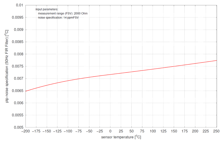 Fig.80: Diagram noise ENoise, PtP in dependence on sensor temperature
5) the 50/60 Hz filter setting must be selected via the settings in the CoE depending on the local mains frequency (50 or 60 Hz); the respective nominal mains frequency then applies as the measuring point for common mode rejection or crosstalk.