Measurement SG 1/2 bridge (half bridge) 3/5-wire connection
Some notes to ELM350x half bridge measurement:
The nominal/technical measuring range is specified in "mV/V"; the maximum permitted supply voltage is 5 V. The maximum nominal measuring range that can be used for the bridge voltage is therefore ±16 mV/V ⋅ 5 V = ±80 mV; the internal circuits are designed for the 160 mV of the full bridge measurement.
The internal measurement is ratiometric, i.e. the feed voltage and the bridge voltage are not measured absolutely, but as a ratio.
The integrated supply can be used as power supply. An external supply is permitted, as long as 5 V is not exceeded.
The terminal has "real" and "compensated" measuring ranges:
- A "real" measuring range measures electrically as specified e.g., in the range 4 mV/V.
- A "compensated" measuring range helps in applications with a small signal (amplitude) and at the same time a high offset component. It measures in a fixed electrical range (i.e., subject to its electrical specification) and performs a "digital zoom", i.e., increases the resolution. The offset must be eliminated by the integrated ZeroOffset function of the terminal.
The following is the specification given for the 5 wire connection. External line resistances are compensated by the 5 wire connection and the half bridge is detected directly from the measuring channel.
In the 3 wire connection, the terminal generally has the same specification, but its view of the connected half bridge is clouded by the unclear and temperature-dependent lead resistances within cables and connectors. In this respect, the overall system "half bridge + leads + measurement channel" will practically not achieve specification values given below.
The lead resistances (cables, connectors, ...) have an effect especially on the gain error, also depending on the temperature. The gain error can be estimated by:
(R+uv (1 + ∆T ⋅ TcCu) + R-uv(1 + ∆T ⋅ TcCu) )/Rnom with TcCu~3930 ppm/K, Rnom
e.g. 350 Ω and R+uv or R-uv lead resistances respectively.
The use of the measurement channel in the 5 wire connection is recommended.
By a user-side adjustment with a connected bridge sensor, the measurement uncertainity related to gain and offset error can be significant reduced.
The integrated switcheable shunt resistor can be used to generate a predictable detuning or, in case of deviation, a correction factor.
Note: specifications apply for 3.5 V SG excitation and symmetric 350R SG.
To calculate the R1/2 half bridge:
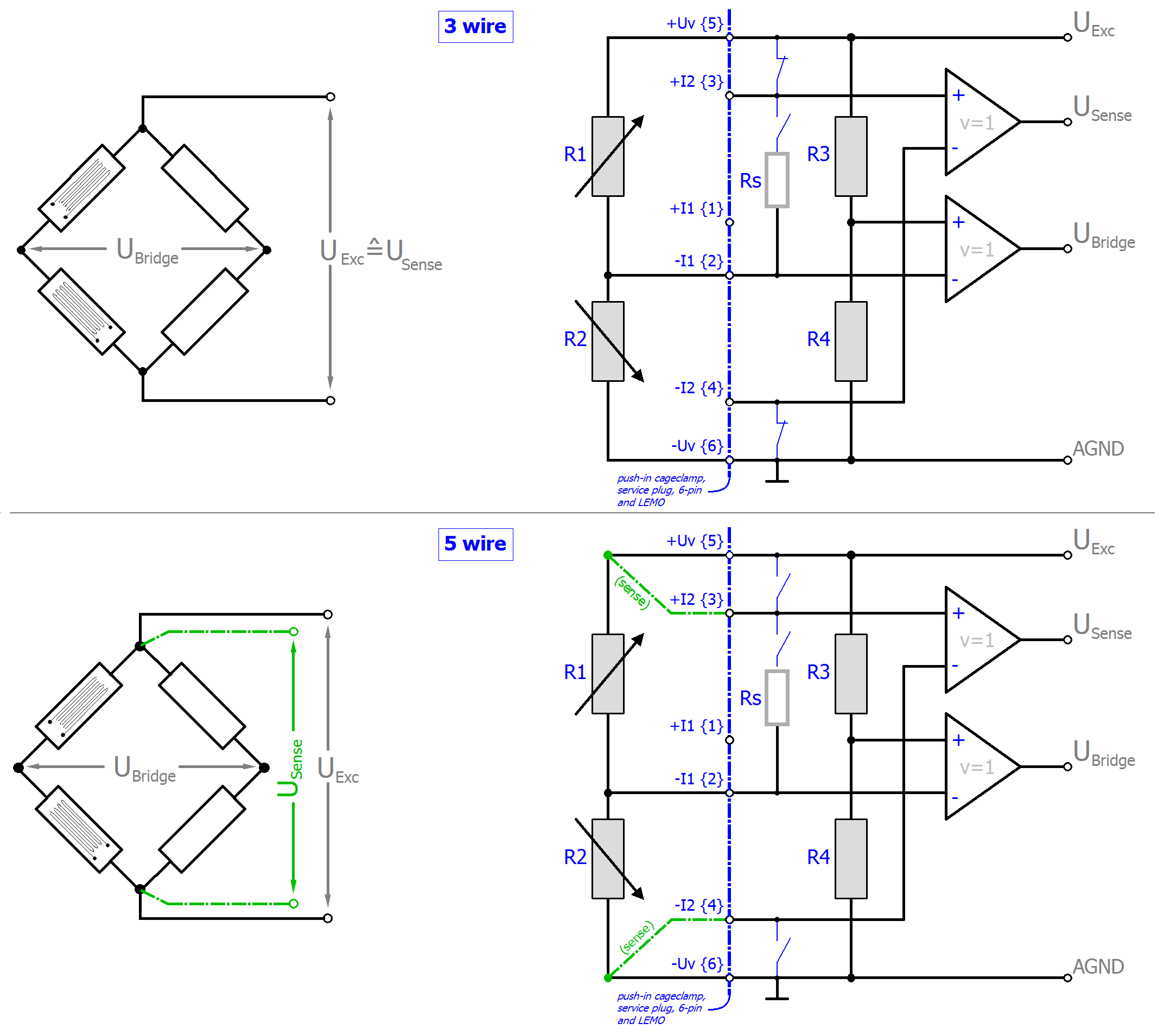
R3/4 are the internal switchable supplementary resistors of the terminal. They have a high resistance of a few kΩ compared to R1/2 and thus do not significantly load the internal supply.
Other half-bridge configurations (e.g. R1/4 or R1/3 variable) cannot be connected.
The strain relationship (µStrain, µε) is as follows:
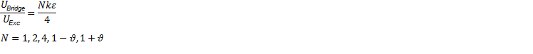
N should be chosen based on the mechanical configuration of the variable resistors (Poisson, 2 active uniaxial, …). The channel value (PDO) is interpreted directly [mV/V].
Measurement mode | Measuring bridge/StrainGauge SG 1/2-Bridge 5/3-wire | ||||||
|---|---|---|---|---|---|---|---|
| 16 mV/V | 8 mV/V 1) | 4 mV/V 1) | 2 mV/V 1) | 4 mV/V (comp.) 1) 5) | 2 mV/V (comp.) 1) 5) | |
Integrated power supply | 1…5V adjustable, max. power supply/Excitation 21 mA (internal electronic overload protection) therefore | ||||||
Measuring range, nominal | -16 … 16 mV/V | -8 … 8 mV/V | -4 … 4 mV/V | -2 … 2 mV/V | -4 … 4 mV/V | -2 … 2 mV/V | |
Measuring range, end value (FSV) | 16 mV/V | 8 mV/V | 4 mV/V | 2 mV/V | 4 mV/V | 2 mV/V | |
Measuring range, technically usable | -17.179 … 17.179 mV/V | -8.589 … 8.589 mV/V | -4.294 … 4.294 mV/V | -2.147 … 2.147 mV/V | -4.294 … 4.294 mV/V | -2.147 … 2.147 mV/V | |
PDO resolution | 24 bit (including sign) | ||||||
PDO LSB (Extended Range) | 0.128 ppm | ||||||
PDO LSB (Legacy Range) | 0.119… ppm | ||||||
Basic accuracy: Measuring deviation at 23°C, with averaging, typ. 2) 6) | without Offset
| < ±0.011 %FSV
| < ±0.022 %FSV
| < ±0.044 %FSV
| < ±0.0925 %FSV
| < ±0.044 %FSV
| < ±0.088 %FSV
|
incl. Offset | < ±0.04 %FSV
| < ±0.075 %FSV
| < ±0.14 %FSV
| < ±0.27 %FSV
| < ±0.15 %FSV
| < ±0.3 %FSV
| |
Extended basic accuracy: Measuring deviation at 0…55°C, with averaging, typ. 2) 6) | without Offset
| < ±0.049 %FSV
| < ±0.082 %FSV
| < ±0.149 %FSV
| < ±0.2955 %FSV
| < ±0.164 %FSV
| < ±0.3275 %FSV
|
incl. Offset | < ±0.0645 %FSV
| < ±0.113 %FSV
| < ±0.2065 %FSV
| < ±0.403 %FSV
| < ±0.2255 %FSV
| < ±0.4505 %FSV
| |
Offset/Zero point deviation (at 23°C) | EOffset | < 385 ppmFSV | < 715 ppmFSV | < 1325 ppmFSV | < 2530 ppmFSV | < 1430 ppmFSV | < 2860 ppmFSV |
Gain/scale/amplification deviation (at 23°C) | EGain | < 70 ppm | < 130 ppm | < 260 ppm | < 510 ppm | < 260 ppm | < 520 ppm |
Non-linearity over the whole measuring range | ELin | < 85 ppmFSV | < 175 ppmFSV | < 350 ppmFSV | < 760 ppmFSV | < 350 ppmFSV | < 700 ppmFSV |
Repeatability, over 24 h, with averaging | ERep | < 12 ppmFSV | < 25 ppmFSV | < 50 ppmFSV | < 120 ppmFSV | < 50 ppmFSV | < 100 ppmFSV |
Temperature coefficient, typ. | TcGain | < 5 ppm/K | < 8 ppm/K | < 15 ppm/K | < 25 ppm/K | < 16 ppm/K | < 32 ppm/K |
TcOffset | < 15 ppmFSV/K | < 25 ppmFSV/K | < 45 ppmFSV/K | < 90 ppmFSV/K | < 50 ppmFSV/K | < 100 ppmFSV/K | |
Common-mode rejection ratio (without filter) 3) | DC | tbd. | tbd. | tbd. | tbd. | tbd. | tbd. |
50/60 Hz: | tbd. | tbd. | tbd. | tbd. | tbd. | tbd. | |
1 kHz | tbd. | tbd. | tbd. | tbd. | tbd. | tbd. | |
Common-mode rejection ratio (with 50/60 Hz: FIR Filter) 3) 4) | DC | DC: | DC: | DC: | DC: | DC: | DC: |
50/60 Hz: | tbd. | tbd. | tbd. | tbd. | tbd. | tbd. | |
1 kHz | tbd. | tbd. | tbd. | tbd. | tbd. | tbd. | |
Largest short-term deviation during a specified electrical interference test | tbd. | tbd. | tbd. | tbd. | tbd. | tbd. | |
Input impedance ±Input 1 (internal resistance) | Differential | tbd. | tbd. | tbd. | tbd. | tbd. | tbd. |
CommonMode | tbd. | tbd. | tbd. | tbd. | tbd. | tbd. | |
Input impedance ±Input 2 (internal resistance) | 3-wire | No usage of this input in this mode | |||||
Differential | tbd. | tbd. | tbd. | tbd. | tbd. | tbd. | |
CommonMode | tbd. | tbd. | tbd. | tbd. | tbd. | tbd. | |


ELM3502 (20 ksps)
|
Measurement mode |
Measuring bridge/StrainGauge SG 1/2-Bridge 5/3-wire | ||||
|---|---|---|---|---|---|
|
|
16 mV/V |
8 mV/V |
4 mV/V |
2 mV/V | |
|
Noise (without filtering, at 23°C) |
ENoise, PtP |
< 600 ppmFSV
|
< 1200 ppmFSV
|
< 2400 ppmFSV
|
< 4800 ppmFSV
|
|
ENoise, RMS |
< 100 ppmFSV
|
< 200 ppmFSV
|
< 400 ppmFSV
|
< 800 ppmFSV
| |
|
Max. SNR |
> 80.0 dB |
> 74.0 dB |
> 68.0 dB |
> 61.9 dB | |
|
Noisedensity@1kHz |
< 22.63 |
< 22.63 |
< 22.63 |
< 22.63 | |
|
Noise (with 50/60 Hz: FIR Filter, at 23°C) 4) |
ENoise, PtP |
< 35 ppmFSV
|
< 70 ppmFSV
|
< 140 ppmFSV
|
< 280 ppmFSV
|
|
ENoise, RMS |
< 6.0 ppmFSV
|
< 12.0 ppmFSV
|
< 22.0 ppmFSV
|
< 45.0 ppmFSV
| |
|
Max. SNR |
> 104.4 dB |
> 98.4 dB |
> 93.2 dB |
> 86.9 dB | |

ELM3504 (10 ksps)
|
Measurement mode |
Measuring bridge/StrainGauge SG 1/2-Bridge 5/3-wire | ||||
|---|---|---|---|---|---|
|
|
16 mV/V |
8 mV/V |
4 mV/V |
2 mV/V | |
|
Noise (without filtering, at 23°C) |
ENoise, PtP |
< 600 ppmFSV
|
< 1200 ppmFSV
|
< 2400 ppmFSV
|
< 4800 ppmFSV
|
|
ENoise, RMS |
< 100 ppmFSV
|
< 200 ppmFSV
|
< 400 ppmFSV
|
< 800 ppmFSV
| |
|
Max. SNR |
> 80.0 dB |
> 74.0 dB |
> 68.0 dB |
> 61.9 dB | |
|
Noisedensity@1kHz |
< 22.63 |
< 22.63 |
< 22.63 |
< 22.63 | |
|
Noise (with 50/60 Hz: FIR Filter, at 23°C) 4) |
ENoise, PtP |
< 35 ppmFSV
|
< 70 ppmFSV
|
< 140 ppmFSV
|
< 280 ppmFSV
|
|
ENoise, RMS |
< 6.0 ppmFSV
|
< 12.0 ppmFSV
|
< 22.0 ppmFSV
|
< 45.0 ppmFSV
| |
|
Max. SNR |
> 104.4 dB |
> 98.4 dB |
> 93.2 dB |
> 86.9 dB | |
1) Adjustment of the half-bridge measurement and thus validity of the data from production week 2018/50 and for ELM3502: HW03/ for ELM3504: HW04
2) In real bridge measurement, an offset adjustment is usually carried out after installation. The given offset specification of the terminal is therefore practically irrelevant. Therefore, specification values with and without offset are given here. In practice, the offset component can be eliminated by the functions ELM Features and also ELM Features of the terminal or in the controller by a higher-level tare function. The offset deviation of a bridge measurement over time can change, therefore Beckhoff recommends a regular offset adjustment or careful observation of the change.
3) Values related to a common mode interference between SGND and internal ground.
4) the 50/60 Hz filter setting must be selected via the settings in the CoE depending on the local mains frequency (50 or 60 Hz); the respective nominal mains frequency then applies as the measuring point for common mode rejection or crosstalk.
5) The channel measures electrically to 8 mV/V, but displays its measured value scaled to 2 or 4 mV/V. The Compensated function facilitates measurement of low levels even with high offset.
6) Calculated value according to the equation for estimating usability at the given ambient temperature point or estimating usability over the specified ambient temperature range in operation (Tambient) as stated in chapter "General information on measuring accuracy/measurement uncertainty". In real use, for example at a relatively constant ambient temperature Tambient, a lower (better) achievable uncertainty is attained. A specific calculation according to chapter "General information on measuring accuracy/measurement uncertainty" is recommended, especially if the instrument allows a wider ambient temperature range in operation than 0...55 °C.
Notice | |
Transition resistances of the connection contacts The transition resistance values of the connection contacts affect the measurement. The measuring accuracy can be further increased by a user-side adjustment with the signal connection plugged in. |
 | Validity of property values The resistor of the bridge is positioned parallel to the internal resistor of the terminal and leads to an offset shifting respectively. The Beckhoff factory calibration will be carried out with the half bridge 350 Ω, thus the values specified above are directly valid for the 350 Ω half bridge. By connection of another dimensioned half-bridge is to:
|