Installation positions
Notice | |
Constraints regarding installation position and operating temperature range Please refer to the technical data for a terminal to ascertain whether any restrictions regarding the installation position and/or the operating temperature range apply. When installing high power dissipation terminals, ensure that adequate spacing is maintained between other components above and below the terminal during operation in order to guarantee adequate ventilation! |
Installation positions and their names for DIN rail-mounted devices are defined below. The illustrations show some typical setups and also apply to DIN rail-mounted devices that are not shown, provided that this chapter is part of the relevant device documentation.
Horizontal installation (standard installation)
The standard installation position defines the device faces: top/bottom, front/rear, right/left, see Fig. "Recommended distances for standard installation position").
In the horizontal installation position, the mounting rail is mounted horizontally on a vertical mounting plate; the connection points for the terminals face forwards. The terminals are ventilated from below, which enables optimum cooling of the electronics through convection.
Reference direction is downwards (see arrow): this shows the direction of the earth's gravitational force
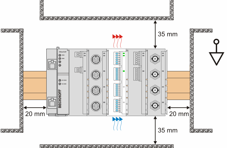 Fig.359: Recommended distances for standard installation position
 Compliance with the distances shown in Fig. “Recommended distances for standard installation position” is also recommended for all other installation positions.
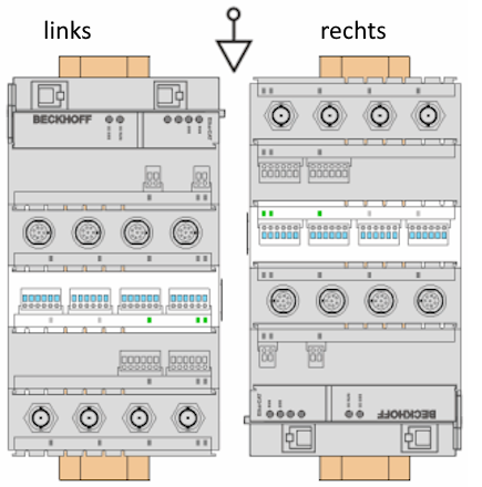
Vertical installation
In the vertical installation position, the mounting rail is mounted vertically on a vertical mounting plate; the connection points for the terminals face forwards. The underside of the device (in relation to the standard installation position) sometimes faces
- Left: Device/terminal sequence descends (facing downwards)
- Right: Device/terminal sequence ascends (facing upwards)
Reference direction is downwards (see arrow): this shows the direction of the earth's gravitational force
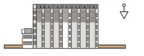
Flat installation
In the flat installation position, the mounting rail is laid on a horizontal mounting plate; the connection points for the terminals face upwards.
Reference direction is downwards (see arrow): this shows the direction of the earth's gravitational force
Installation position names
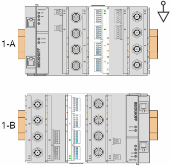 Fig.360: Mounting rail with terminal block mounted horizontally on a lateral surface
- 1-A: Mounted laterally, from left to right
- 1-B: Mounted laterally, from right to left
Other installation positions
All of the other installation positions (2-A, 2-B, and 3-A, 3-B) are characterized by different positions of the mounting rail which deviate from the optimal position.
The minimum distances to the environment as specified above also apply for these installation positions.
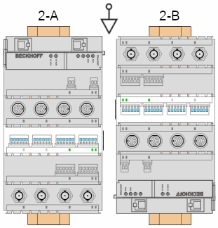 Fig.361: Support rail with terminal block mounted vertically on a lateral surface
- 2-A: Mounted laterally, from top to bottom
- 2-B: Mounted laterally, from bottom to top
 Fig.362: Mounting rail with terminal block mounted on a surface facing upwards or downwards
- 3-A: Mounting rail underneath, connection side faces upwards
- 3-B: Mounting rail at top, connection side faces downwards