Measurement IEPE 0…20 V
|
Measurement mode |
0…20 V | |
|---|---|---|
|
Internal resistance |
>4 MΩ differential | |
|
Impedance |
Value to follow | |
|
Measuring range, nominal |
0…20 V | |
|
Measuring range, end value (FSV) |
20 V | |
|
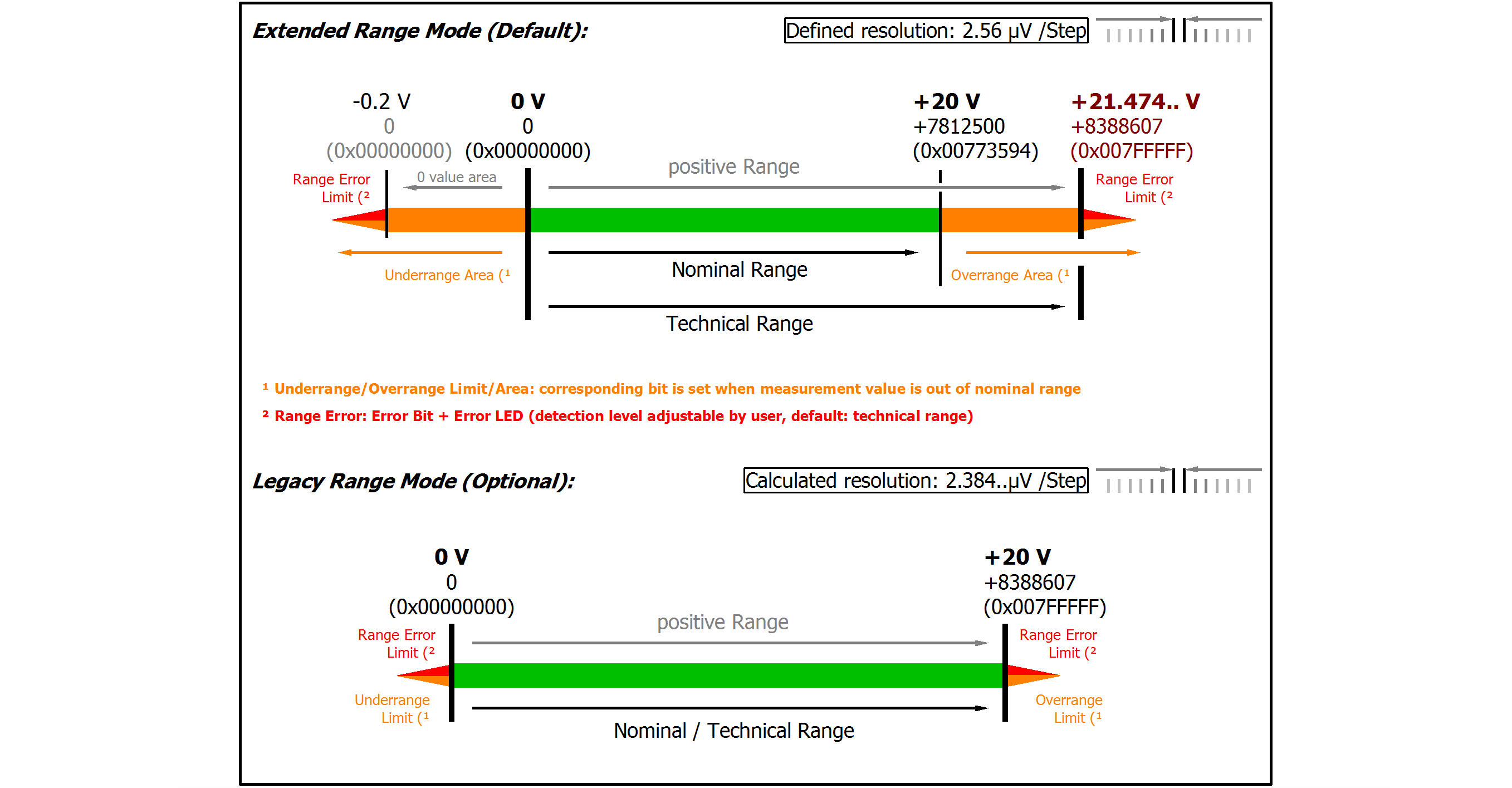
Measuring range, technically usable |
0…+21.474 V | |
|
PDO resolution (unsigned) |
23 bit |
15 bit 2) |
|
PDO LSB (Extended Range) |
2.56 µV |
655.36 µV |
|
Input impedance ±Input 1 (internal resistance) |
Differential typ. (tbd) || (tbd) CommonMode typ. (tbd) against SGND | |
2) The analog measurement is always done with 24 bits, in 16-bit mode the eight least significant bits are cut off. For further information see chapter “Commissioning”/ “Process data overview”
Preliminary specifications
|
Measurement mode |
0…20 V | ||||
|---|---|---|---|---|---|
|
Basic accuracy: Measuring deviation at 23°C, with averaging |
< ±0.01% = 100 ppmFSV typ. | ||||
|
Offset/Zero point deviation (at 23°C) |
EOffset |
< 70 ppmFSV | |||
|
Gain/scale/amplification deviation (at 23°C) |
EGain |
< 60 ppm | |||
|
Non-linearity over the whole measuring range |
ELin |
< 25 ppmFSV | |||
|
Repeatability, over 24 h, with averaging |
ERep |
< 20 ppmFSV | |||
|
Noise (without filtering) |
ENoise, PtP |
< 100 ppmFSV |
< 781 [digits] | ||
|
ENoise, RMS |
< 18 ppmFSV |
< 141 [digits] | |||
|
Max. SNR |
> 94.9 dB | ||||
|
Noisedensity@1kHz |
< 2.55
| ||||
|
Noise (with 50 Hz FIR filter) |
ENoise, PtP |
< 10 ppmFSV |
< 78 [digits] | ||
|
ENoise, RMS |
< 2.0 ppmFSV |
< 16 [digits] | |||
|
Max. SNR |
> 114.0 dB | ||||
|
Temperature coefficient |
TcGain |
< 8 ppm/K typ. | |||
|
TcOffset |
< 5 ppmFSV/K typ. | ||||
|
Common-mode rejection ratio (without filter) |
DC: >115 dB typ. |
50 Hz: >105 dB typ. |
1 kHz: >80 dB typ. | ||
|
Common-mode rejection ratio (with 50 Hz FIR filter) |
DC: >115 dB typ. |
50 Hz: >115 dB typ. |
1 kHz: >115 dB typ. | ||
|
Largest short-term deviation during a specified electrical interference test |
±0.03% = 300 ppmFSV typ. | ||||

|
Note: The channel also works in electrically bipolar mode and records negative values in the unipolar measuring ranges (measurement from 0 V, 0 mA, 4 mA, 0 Ω). This enables the channel to provide a precise diagnosis even with signals < 0. In these measuring ranges the limit value for the "Underrange Error" in Extended Mode is -1% of the full scale value (FSV). The limit value can be set in CoE object 0x80n0:32. This avoids irritating error messages if the channel is not wired (e.g. without sensor) or the electrical signal fluctuates slightly around zero. The process data value of 0x00000000 is not undershot. If the "UnderrangeError" detection is to be set even less sensitive, the magnitude of the negative limit value in the CoE object referred to above can be set even higher. |