Recommendations for use
Comparison of properties depending on switching technology
Technology | Reed | FET/Solid State | EMR, Electromagnetic Relay |
|---|---|---|---|
Examples | ELM264x, EL264x | ELM274x, EL27xx | EL26xx |
Switching characteristics | "real" switch, completely disconnects | semiconductor switches, always low leakage current | "real" switch, completely disconnects |
Transition resistance | Higher | Low | Low |
Repeat stability Ron | Good | Very well | Very well |
Overload behavior | Sensitive | Less sensitive | Sensitive |
Switching speed **) | Fast | Very fast | Medium |
Dependence of properties on the ambient temperature | Low | Higher | Low |
Leakage current when open | Very low | Higher, increasing with operating temperature, several nA | Very low |
Resulting offset/thermovoltage | Yes, several ±10 µV | Low, a few ±1 µV | Yes, higher than reed, also due to self-heating |
Wear | Yes, gradual aging with normal use Typ. failure: non-conductive | Low, if at all, then sudden failure Typ. failure: conductive | Yes, gradual aging with normal use Typ. failure: non-conductive |
AC behavior (alternating signals), crosstalk | Good | Less good, to be assessed applicatively | Good |
Recommended use | Use at fluctuating ambient temperature 4-wire resistance measurements | Use at room temperature 2-wire resistance measurements Thermocouples (as long as the ambient temperature does not change significantly) Current peaks Frequent/fast switching |
|
2) it is not so much the Ton/Toff time of the switching element that is decisive with regard to the switching speed, but rather the time it takes for the device's internal firmware to control the switches.
If a switching element such as the EL2xxx/ELM2xxx is used for the manipulation of demanding analog signals, it should always be borne in mind that temperature changes affect properties of all kinds and can change them adversely. This must be taken into account when designing the system.
In addition, the switching elements always bring ohmic/inductive/capacitive influences into the system. Offset matching is recommended for voltage or resistance measurement.
In general, "complete" all-pole switching of the signals is recommended, i.e. all six lines in the case of a 6-wire DMS connection. If this is deviated from and, for example, only the signal line (+) is switched in a 2-pin IEPE connection
- earth loop(s) may be created, depending on the design of the sensor and wiring,
- interference inductions are facilitated by an N-fold enlarged line network,
- the switched signal is to be given a sufficient settling time, e.g. a constant IEPE current signal must first stabilize for a few 100 ms,
- "bouncing" can occur when mechanical contacts close,
- the switched devices must be suitable for the on/off switching operation,
- in the case of resistance simulation, the parallel circuit
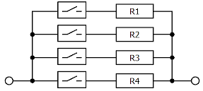
can be used.
To get nearly equal resistance gradations with as many switching combinations as possible, the serial circuit with e.g. binary stepped values is recommended: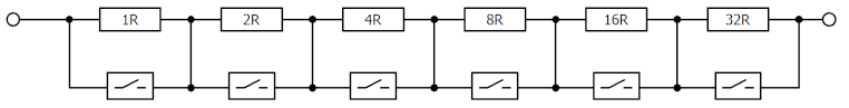 .
.
It requires switches that are accessible on both sides, such as provided by the EL2624. - To create a resistance simulation based on this serial circuit with the multiplex terminals is only possible with two switches of a group of 4 switches:
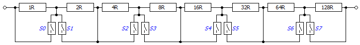
A combination of both circuit types leads to further possible resistance values and partially redundant switching combinations.
Like any technical device, a switching terminal can fail: on the one hand by non-switching although it is supposed to switch, e.g. "contact destroyed" and, on the other hand, by permanent connection although it is supposed to disconnect, e.g. "contact sticks". Sufficient plausibility queries should be provided for this purpose on the receiving side.
Additional notes:
- An external protective circuit is necessary with inductive/capacitive loads, e.g. a short-circuit diode.
- External strong magnetic fields or vibrations/shocks can affect the function, for example, of reed relays
- The devices discussed here have switching cycle counters in the CoE and it is recommended to observe them.
- With long/frequent use, aging switching contacts exhibit a slowly increasing resistance before complete failure. Occasional checking of the switching function can be useful.
- The repair of individual switches in the Beckhoff Service Dept. is possible.
Concrete examples of MUX applications with Beckhoff analog inputs
RTD to EL320x terminals
- Multiplexing introduces transition resistances into the sensor connection. Therefore, for the combination RTD + multiplexing, the 4-wire connection with +R(UExc), +RL(+sense), -RL(-sense) and -R(AGND) is recommended.
- The 4-wire connection is supported, for example, by the EL3201-xxxx, EL3202-xxxx, EL3751, ELM350x, ELM370x and others.
- An EL320x is only designed to supply one RTD sensor. Therefore, the +R/UExc connection cannot be used to power multiple RTD sensors. So it can't be muxed.
- -R(AGND) can be connected through for multiple RTDs, so it does not need to be muxed.
- +RL(+sense) and -RL(-sense) must be muxed as feedback lines.
- Terminals from the ELM26xx, ELM27xx or EL26xx series can be used for multiplexing.
Interference of multiplexers in the signal curve
Ideally, the sensor and the evaluation input (measuring device) are connected directly (without connectors) and via the shortest possible cable. The insertion of multiplexers (or other elements, such as connectors, extension cables, etc.) between the sensor and the evaluation input therefore fundamentally changes the direct signal flow from source to sink in a real setup. This is intentional when the switch is open, but also especially - rather unintentionally - when the switch is closed. The switching element, including the necessary cables and plug-in transitions, generally generate interference that changes or falsifies the measurement results. This must generally be observed when using switches in the signal flow. Depending on the type of signal, the special operation of the switches in multiplex mode also has an influence on the signal; among other things, crosstalk, attenuation and reflections may occur and settling times may have to be taken into account during switching operations.
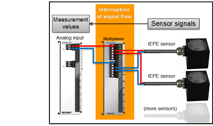 Fig.6: Interruption of the "direct" signal flow of the sensor signals to the measurement input in the real setup
Potential influence of switches on high-frequency signals
Depending on signal frequency/frequencies and amplitude (signal strength), frequency-dependent effects may occur in the multiplexer and between the unavoidable lines. Here are some observations and notes:
- Crosstalk
- "Real" switches such as EMR and reed separate "exemplarily"; crosstalk attenuation values of -90 dB have been observed (the larger the value the greater the signal distance between the interferer and victim channels, i.e. the better the crosstalk attenuation).
- Semiconductor switches (FET, SolidState) have a feedback effect on the control due to their non-electrical isolation and thus crosstalk into adjacent switches, starting with a crosstalk attenuation of -80 dB at 100 Hz, at frequencies from 1 kHz up to -60 dB were observable. The values given do not represent specification values, but are intended to provide orientation for your own application-specific considerations.
- Attenuation
- Attenuations of less than -0.02 dB were determined for each switch in the range 0...1 kHz, corresponding to approx. 0.23 % (2300 ppm) amplitude.
- Semiconductor switches tend to have somewhat lower attenuation.
- Reflections
- no observations available yet.
Potential influence of switches on IEPE signals
IEPE sensors generate an offset voltage (bias) of approx. 10..14 V, on which the information-relevant AC voltage of, for example, ±5 V is modulated. The offset voltage must first be adjusted after switching on; the high-pass (HP) filter, which is usually present, must first settle in order to suppress the DC offset for evaluation (the faster (i.e. higher) the HP filter frequency is set, the faster the settling takes place, but the less sensitive the measurement becomes for low-frequency signals).
All in all, this results in the effect that a settling time must be observed after the switch-on process. With direct connections between sensor and evaluation unit, it is necessary to wait for settling to complete once at the start of operation. In industrial plants, whose ramp-up times can be considerable, the settling time is therefore often not even noticed.
In multiplexing mode, however, the supply of current-supplied sensors is interrupted with each switchover and the bias voltage must constantly be re-established by the subsequent switch-on process in this operation mode. Measured data recorded during the settling time are to be considered invalid. In order to minimize the loss of system performance when signal monitoring is required to assess the validity of the measured data, it is instead advisable to determine the settling time as a function of relevant parameters. This allows a delay time to be taken into account in the measuring system between switching over and the start of measurement, which does not last longer than necessary. The duration of the settling time depends on (in descending order of weighting):
- high-pass filter settings in the measuring device (e.g. ELM3602 or EL3632),
- the IEPE current intensity (2, 4, ... mA: the higher, the shorter the settling time),
- cable length (the longer, the longer the settling time),
- cable diameter (the thicker, the shorter the settling time),
- from the design of the IEPE sensor
and can range from a few seconds to the high minute range.
The following diagram shows examples of settling times during switch-on processes with one of the combinations of ELM3602 (24 bits, 50 kSps) and ELM2742 (SolidState):
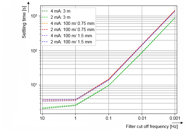 Fig.7: Examples of settling time as a function of filter cut-off frequency (ELM3602 in combination with ELM2742)
Recommended procedure: if a high-pass filter can be set in the measuring device by the control unit and ideally the IEPE current can also be set/ switched off, the following procedure could be used in the event of a switchover:
- Set a “fast” settling time: HP filter IEPE AC coupling 0.1 Hz -> 10 Hz and wait approx. 100 ms
- Switch off the IEPE BIAS current and wait approx. 100 ms (protects the switching contacts)
- Switch the multiplexer via the controller and wait approx. 100 ms
- Switch on the IEPE BIAS current (e.g. 4 mA) and wait approx. 1 sec (settling time)
- Set a “slow” or task-specific settling time: Filter IEPE AC coupling 10Hz -> 0.1 Hz and wait approx. 100 ms
- Start of measurement/evaluation
It is necessary that these settings are possible in the measuring device and that the measured value is not changed by the filter switchover, e.g. with the ELM360x IEPE terminal.