Chopper operation
You can connect a brake resistor (chopper) instead of a DC motor to a channel of the EL7332/EL7342 and activate the operating mode Brake resistor (EL7332, index 0x8022:01 or 0x8032:01; EL7342, index 0x8022:01 or 0x8032:01) for this channel.
The motor must actively brake for positioning tasks. The mechanical energy is thereby converted back into electrical energy. Small quantities of energy are taken up by a capacitor in the EL7332/EL7342. Further storage capacities, for example in the power supply, can also take up energy. The feedback leads in each case to a voltage increase.
In order to avoid overvoltage, a brake resistor can be connected to the EL7332/EL7342 in order to dissipate the excess energy in the form of heat. As soon as the voltage reaches 110% of the nominal voltage (EL7332, index 0x8020:03 or 0x8030:03; EL7342, 0x8020:03 or 0x8030:03), e.g. 55 V for the EL7342, the correctly adjusted output stage drives a fast-clocked current through the brake resistor (see diagram).
 Fig.168: ICH/IN. - UCH/UN characteristic curve
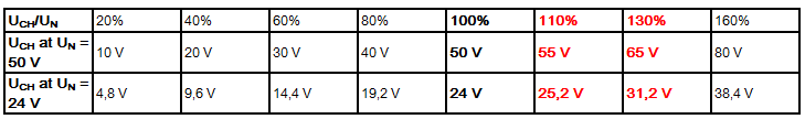
Notice | |
Dimensioning of the brake resistor The brake resistor should be dimensioned such that it can withstand the expected heat development without damage! |
A brake resistance of 10 Ω is recommended for EL7342, which results in a pulse current of approx. 5.5 A to 6.5 A. The maximum expected continuous power is 125 W. However, the value typically lies significantly below that.
Power estimation
PN = IN² x R
PN = (5A)² x 10 Ω
PN = 250 W
A maximum duty cycle of 50 % is possible. This results in a maximum continuous power of 125 W.
A motor efficiency of 80 % is usual in practice.
The motor thus converts 80 % of the rated electrical power into kinetic energy when accelerating.
Conversely, when braking, the motor (as a generator) converts 80 % of the kinetic energy into electrical power.
This results in a practical brake power of:
PCH = PN/2 x 80/100 x 80/100
PCH = 125W x 80/100 x 80/100
PCH = 80 W