TwinSAFE reaction times
The TwinSAFE terminals form a modular safety system that exchanges safety-oriented data via the Safety-over-EtherCAT protocol. This chapter is intended to help you determine the system's reaction time from the change of signal at the sensor to the reaction at the actuator.
Typical reaction time
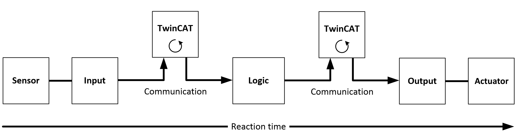
The typical reaction time is the time that is required to transmit information from the sensor to the actuator, if the overall system is working without error in normal operation.
|
Definition |
Description |
|---|---|
|
RTSensor |
Reaction time of the sensor until the signal is provided at the interface. Typically supplied by the sensor manufacturer. |
|
RTInput |
Reaction time of the safe input, such as EL1904 or EP1908. This time can be found in the technical data. In the case of the EL1904 it is 4 ms. |
|
RTComm |
Reaction time of the communication This is typically 3x the EtherCAT cycle time, because new data can only be sent in a new Safety-over-EtherCAT telegram. These times depend directly on the higher-level standard controller (cycle time of the PLC/NC). |
|
RTLogic |
Reaction time of the logic terminal. This is the cycle time of the logic terminal and typically ranges from 500 µs to 10 ms for the EL6900, depending on the size of the safety project. The actual cycle time can be read from the terminal. |
|
RTOutput |
Reaction time of the output terminal. This typically lies within the range of 2 to 3 ms. |
|
RTActor |
Reaction time of the servo terminal from the cut-off of the 24 V at the terminal point until the safe cut-off of the gate driver (Under Voltage Lockout). This time is typically about 20 ms. |
|
WDComm |
Watchdog time of the communication |
This results in the following equation for the typical-case reaction time:

with, for example

Worst-case reaction time
The worst case reaction time is the maximum time required to switch off the actuator in the case of an error.
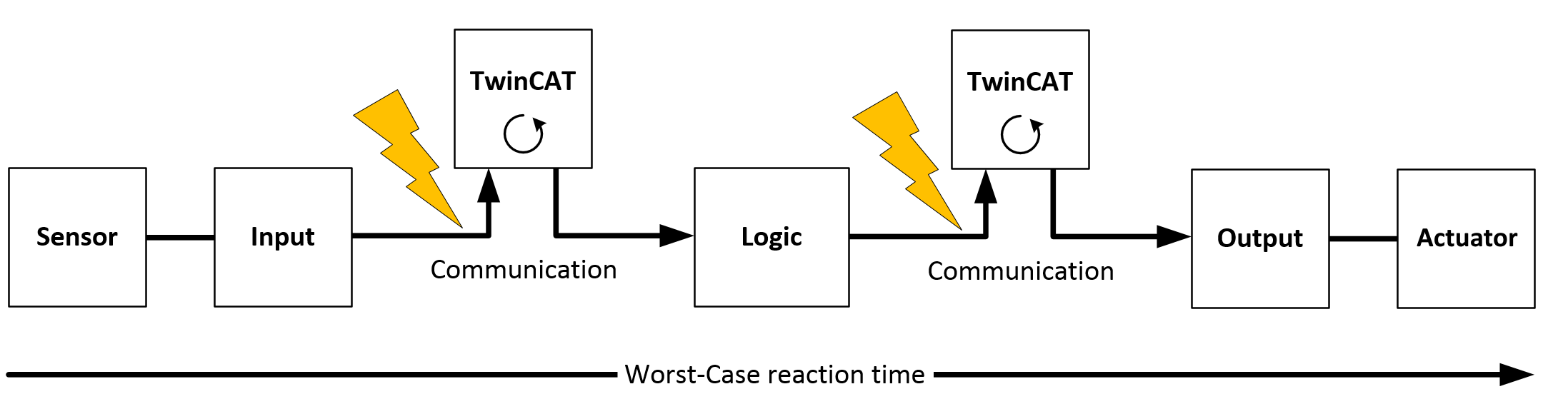
This assumes that a signal change occurs at the sensor and is transmitted to the input. A communication error occurs at precisely the moment when the signal is to be transferred to the communication interface. This is detected by the logic following the watchdog time of the communication link. This information should then be transferred to the output, but a further communication error occurs here. This error is detected at the output following the expiry of the watchdog time and leads to the switch-off.
This results in the following equation for the worst-case reaction:

with, for example
