Application example for STO function (Cat. 3, PL d)
Application example (STO – Safe Torque Off)
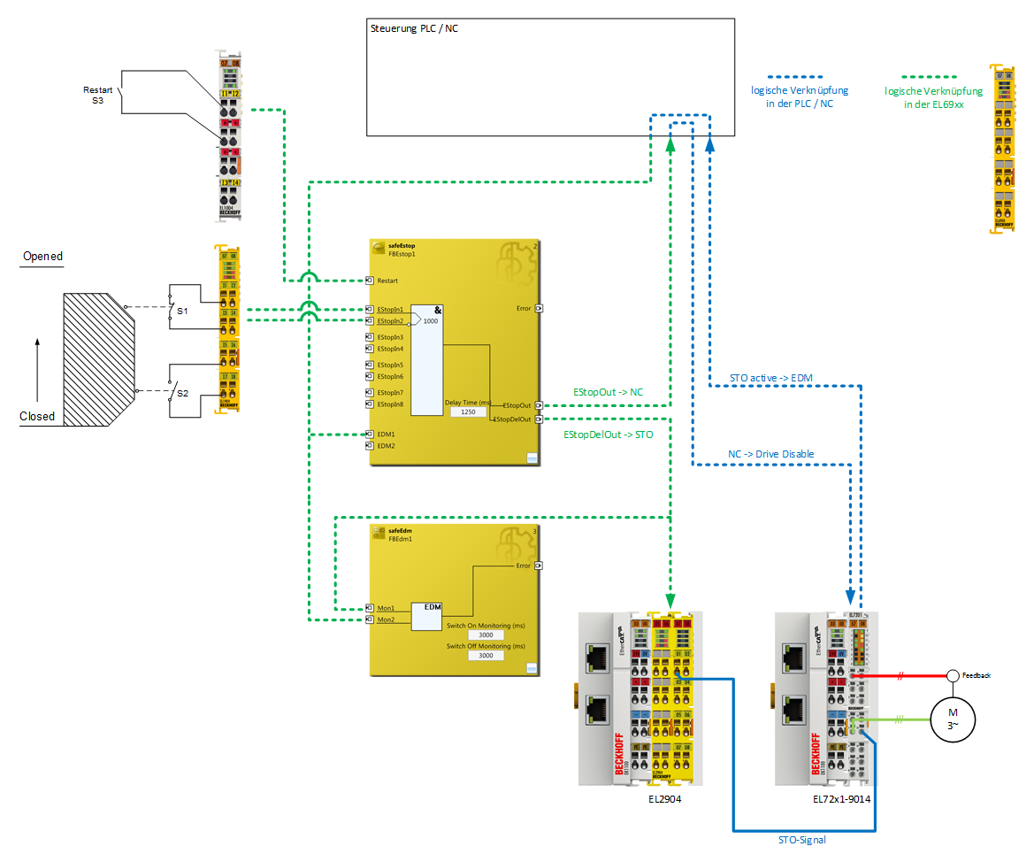
The following application example shows how the EL72x1-9014 can be wired together with an EL2904 in order to implement an STO function according to EN 61800-5-2.
The user must realize an appropriate evaluation for the wiring between the safety output terminal (EL2904) and the servo terminal (EL72x1-9014), so that a fault exclusion is permissible for external supply and cross-circuit in this wiring.
Components involved
- Emergency stop device (control switch S1) according to ISO 13850 and control switch S2
- 1 safety input terminal (EL1904) and 1 input terminal (EL 1004)
- 1 safety output terminal (EL2904)
- 1 safety logic terminal (EL6900) with function block "ESTOP"
- 1 servo terminal (EL72x1-9014) with STO input
- Programmable logic controller (PLC) and EtherCAT fieldbus
A safety door (S1 and S2) and a restart signal (S3) are logically linked on an ESTOP function block. The EStopOut signal is transferred to the NC controller, with which, for example, the Enable signal of the EL72x1-9014 can be switched. The STO input of the EL72x1-9014 is operated via the delayed output EStopDelOut. The EL72x1-9014 supplies the information that the STO function is active via the standard controller. This information is transferred to the EDM input of the ESTOP function block and additionally to the EDM function block in order to generate an expectation for this signal.
| |
Implement a restart lock in the machine! The restart lock is NOT part of the safety chain and must be implemented in the machine! |

| |
Wiring only inside the control cabinet The wiring between the EL2904 and the STO input of the EL72x1-9014 must be located in the same control cabinet in order to be able to assume a fault exclusion for the cross-circuit or external power supply of the wiring between EL2904 and EL72x1-9014. |
 | Calculation EL72x1-9014 The EL72x1-9014 is not taken into account in the calculation of the Performance Level DIN EN ISO 13849-1 since it behaves non-reactively to the safety function. The PFH value goes into the calculation according to EN 62061 with a value of 0. |
| Operation of several EL72x1-9014 terminals at the same time A maximum of 10 STO inputs of the corresponding EL72x1-9014 can be operated at the same time with a cut-off channel of the EL2904. |
Parameters of the safe input and output terminals
EL1904
Parameter | Value |
|---|---|
Sensor test channel 1 active | Yes |
Sensor test channel 2 active | Yes |
Sensor test channel 3 active | Yes |
Sensor test channel 4 active | Yes |
Logic channel 1 and 2 | Single Logic |
Logic channel 3 and 4 | Single Logic |
EL2904
Parameter | Value |
|---|---|
Current measurement active | No |
Output test pulses active | Yes |
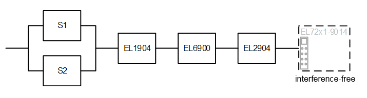
Block formation and safety loops
Safety function 1
Calculation
PFH / MTTFd /B10d – values
Component | Value |
|---|---|
EL1904 – PFH | 1.11E-09 |
EL2904 – PFH | 1.25E-09 |
EL6900 – PFH | 1.03E-09 |
EL72x1-9014 - PFH | 0.00 |
S1 – B10d | 1,000,000 |
S2 – B10d | 2,000,000 |
Days of operation (dop) | 230 |
Hours of operation / day (hop) | 16 |
Cycle time (minutes) (Tcycle) | 15 (4x per hour) |
Lifetime (T1) | 20 years = 175200 hours |
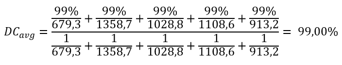
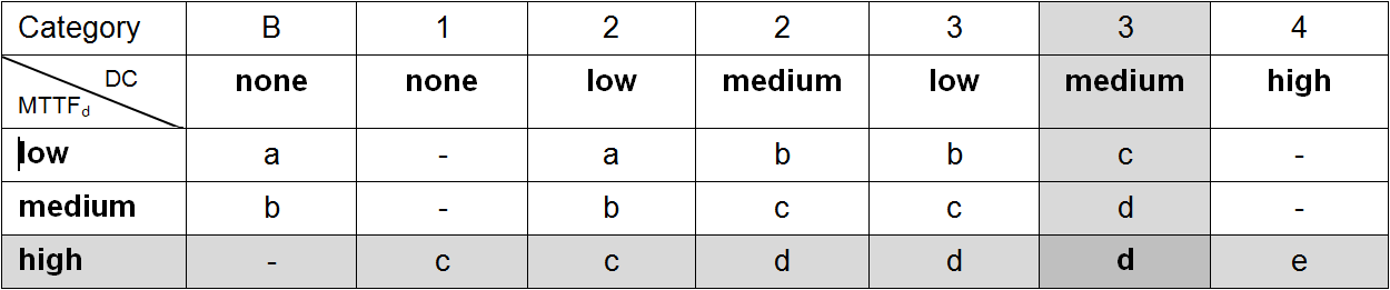
Diagnostic Coverage DC
Component | Value |
|---|---|
S1/S2 with testing/plausibility | DCavg=99% |
EL2904 with testing | DCavg=99% |
Calculation for block 1
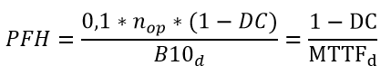
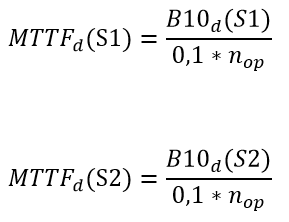
Calculation of the PFH and MTTFd values from the B10d values:
From:
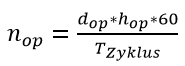
and:
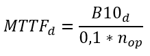
Inserting the values, this produces:
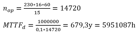
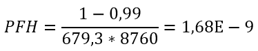
S1:
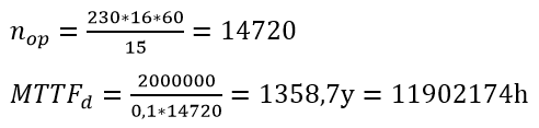
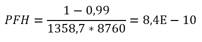
S2:
and the assumption that S1 and S2 are each single-channel:
produces for
S1:
S2:
The following assumptions must now be made:
The door switches S1/S2 are always actuated in opposite directions. Since the switches have different values, but the complete protective door switch consists of a combination of normally closed and normally open contacts and both switches must function, the poorer of the two values (S1) can be taken for the combination!
There is a coupling coefficient between the components that are connected via two channels. Examples are temperature, EMC, voltage peaks or signals between these components. This is assumed to be the worst-case estimation, where ß =10%. EN 62061 contains a table with which this ß-factor can be precisely determined. Further, it is assumed that all usual measures have been taken to prevent both channels failing unsafely at the same time due to an error (e.g. overcurrent through relay contacts, overtemperature in the control cabinet).
This produces for the calculation of the PFH value for block 1:
PFHtot = β* (PFH(S1)+ PFH(S2))/2 + PFH(EL1904) + PFH(EL6900) + PFH(EL2904) + PFH(EL7201-9014)
to:
PFHtot = 10%* (1.68E-09+1.68E-09)/2 +1.11E-09 + 1.03E-09 + 1.25E-09 + 0.00 = 3.558E-09
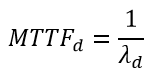
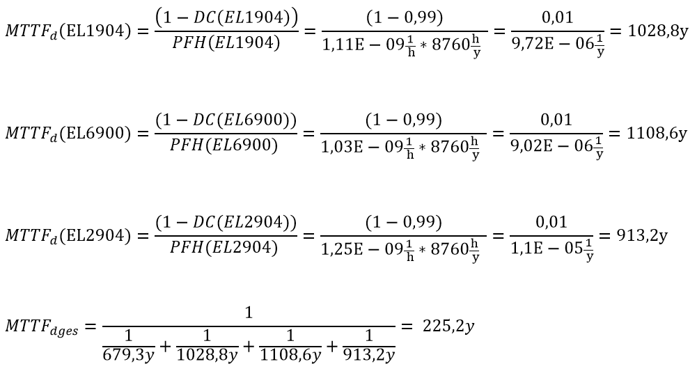
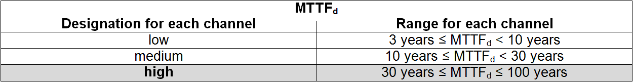
The MTTFd value for block 1 (based on the same assumption) is calculated with:
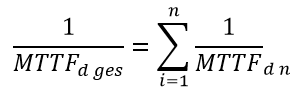
as:

with:
If only PFH values are available for EL1904, EL2904 and EL6900, the following estimation applies:
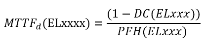
Hence:
| |
Category This structure is possible up to category 3 at the most. |

Manufacturer data for interface type C – Senke
Parameter | min. | typically | max. |
|---|---|---|---|
Class | 2.3 | ||
Test pulse duration ti | - | - | 500 µs |
Test pulse interval T | 10 ms | - | - |
Input resistance R | 4.7 kΩ | - | - |
Input capacitance CL | - | - | 1.21 µF |
The Testing parameter can be switched on in conjunction with the EL2904.