Start types
The Positioning interface offers different types of positioning. The following table contains all commands supported; these are divided into four groups.
Supported “Start types” of the “Positioning interface”
Name | Command | Group | Description |
|---|---|---|---|
ABSOLUTE | 0x0001 | Absolute positioning to a specified target position | |
RELATIVE | 0x0002 | Relative positioning to a calculated target position; a specified position difference is added to the current position | |
ENDLESS_PLUS | 0x0003 | Endless travel in the positive direction of rotation (direct specification of a speed) | |
ENDLESS_MINUS | 0x0004 | Endless travel in the negative direction of rotation (direct specification of a speed) | |
ADDITIVE | 0x0006 | Additive positioning to a calculated target position; a specified position difference is added to the last target position | |
ABSOLUTE_CHANGE | 0x1001 | Dynamic change of the target position during a travel command to a new absolute position | |
RELATIVE_CHANGE | 0x1002 | Dynamic change of the target position during a travel command to a new relative position (the current changing position value is used here also) | |
ADDITIVE_CHANGE | 0x1006 | Dynamic change of the target position during a travel command to a new additive position (the last target position is used here) | |
MODULO_SHORT | 0x0105 | Modulo positioning along the shortest path to the modulo position (positive or negative), calculated by the "Modulo factor" (Index 0x8020:0E) | |
MODULO_SHORT_EXT | 0x0115 | Modulo positioning along the shortest path to the modulo position; the "Modulo tolerance window" (Index 0x8020:0F) is ignored | |
MODULO_PLUS | 0x0205 | Modulo positioning in the positive direction of rotation to the calculated modulo position | |
MODULO_PLUS_EXT | 0x0215 | Modulo positioning in the positive direction of rotation to the calculated modulo position; the "Modulo tolerance window" is ignored | |
MODULO_MINUS | 0x0305 | Modulo positioning in the negative direction of rotation to the calculated modulo position | |
MODULO_MINUS_EXT | 0x0315 | Modulo positioning in the negative direction of rotation to the calculated modulo position; the "Modulo tolerance window" is ignored | |
MODULO_CURRENT | 0x0405 | Modulo positioning in the last direction of rotation to the calculated modulo position | |
MODULO_CURRENT_EXT | 0x0415 | Modulo positioning in the last direction of rotation to the calculated modulo position; the "Modulo tolerance window" is ignored | |
CALI_PLC_CAM | 0x6000 | Start a calibration with cam (digital inputs) | |
CALI_HW_SYNC | 0x6100 | Start a calibration with cam and HW sync pulse (C-track) | |
SET_CALIBRATION | 0x6E00 | Manually set the terminal to "Calibrated" | |
SET_CALIBRATION_AUTO | 0x6E01 | Automatically set the terminal to "Calibrated" on the first rising edge on "Enable" | |
CLEAR_CALIBRATION | 0x6F00 | Manually delete the calibration |
ABSOLUTE
The absolute positioning represents the simplest positioning case. A position B is specified and travelled to from the start point A.
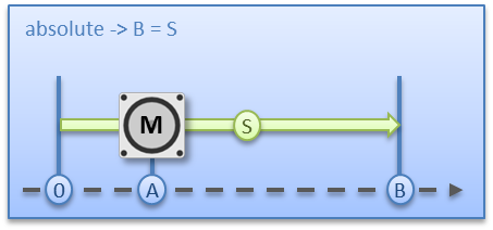 Fig.168: Absolute positioning
RELATIVE
In relative positioning, the user specifies a position delta S, which is added to the current position A, producing the target position B.
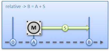 Fig.169: Relative positioning
ENDLESS_PLUS / ENDLESS_MINUS
The two start types ENDLESS_PLUS and ENDLESS_MINUS offer the possibility in the Positioning Interface to specify a direct motor velocity in order to travel endlessly in the positive or negative direction with the specified accelerations.
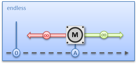 Fig.170: Endless travel
ADDITIVE
For additive positioning, the position delta S specified by the user is added to the target position E used for the last travel command in order to calculate the target position B.
This kind of positioning resembles the relative positioning, but there is a difference. If the last travel command was completed successfully, the new target position is the same. If there was an error, however, be it that the motor entered a stall state or an Emergency stop was triggered, the current position is arbitrary and not foreseeable. The user now has the advantage that he can use the last target position for the calculation of the following target position.
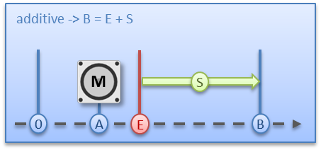 Fig.171: Additive positioning
ABSOLUTE_CHANGE / RELATIVE_CHANGE / ADDITIVE_CHANGE
These three kinds of positioning are completely identical to those described above. The important difference thereby is that the user uses these commands during an active travel command in order to dynamically specify a new target position.
The same rules and conditions apply as to the “normal” start types. ABSOLUTE_CHANGE and ADDITIVE_CHANGE are unique in the calculation of the target position i.e. in absolute positioning an absolute position is specified and in additive positioning a position delta is added to the momentarily active target position.
Notice | |
Caution when using the RELATIVE_CHANGE positioning The change by means of RELATIVE_CHANGE must be used with caution, since the current position of the motor is also used here as the start position. Due to propagation delays in the system, the position indicated in the PDO never corresponds to the actual position of the motor! Therefore a difference to the desired target position always results in the calculation of the transferred position delta. |
 | Time of the change of the target position A change of the target position cannot take place at an arbitrary point in time. If the calculation of the output parameters shows that the new target position cannot be readily reached, the command is rejected by the terminal and the Command rejected bit is set. This is the case, for example, at standstill (since the terminal expects a standard positioning here) and in the acceleration phase (since at this point the braking time cannot be calculated yet). |
CALI_PLC_CAM / CALI_HW_SYNC / SET_CALIBRATION / SET_CALIBRATION_AUTO / CLEAR_CALIBRATION:
The simplest calibration case is calibration by cam only (connected to one digital input).
Here, the motor travels in the 1st step with velocity 1 (Index 0x8020:09) in direction 1 (Index 0x8021:13) towards the cam. Subsequently, in the 2nd step, it travels with velocity 2 (Index 0x8020:0A) in direction 2 (Index 0x8021:14) away from the cam. After the In-Target timeout"(Index 0x8020:0C) has elapsed, the calibration position (Index 0x8020:08) is taken on by the terminal as the current position.
Notice | |
Observe the switching hysteresis of the cam switch With this simple calibration it must be noted that the position detection of the cam is only exact to a certain degree. The digital inputs are not interrupt-controlled and are "only" polled. The internal propagation delays may therefore result in a system-related position difference. |
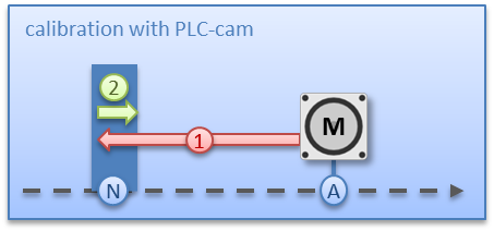 Fig.172: Calibration with cam
For a more precise calibration, an HW sync pulse (C-track) is used in addition to the cam. This calibration proceeds in exactly the same way as described above, up to the point at which the motor travels away from the cam. The travel is not stopped immediately; instead, the sync pulse is awaited. Subsequently, the In-Target timeout runs down again and the calibration position is taken on by the terminal as the current position.
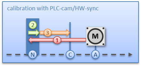 Fig.173: Calibration with cam and C-track
If calibration by hardware is not possible due to the circumstances of the application, the user can also set the Calibrated bit manually or automatically. The manual setting or deletion takes place with the commands SET_CALIBRATION and CLEAR_CALIBRATION.
It is simpler, however, if the standard start types (Index 0x8021:01) are set to SET_CALIBRATION_AUTO. The Calibrated bit will now be set automatically by the first rising edge on Enable. The command is conceived only for this purpose; therefore, it does not make sense to use it via the synchronous data exchange.