TwinCAT System Manager
The TwinCAT System Manager tool is used for the configuration of the EL6752 DeviceNet® master/slave terminal. The System Manager provides a representation of the number of programs of the TwinCat PLC systems, the configuration of the axis control and of the connected I/O channels as a structure, and organizes the mapping of the data traffic.
 Fig.29: TwinCAT System Manager logo
For applications without TwinCAT PLC or NC, the TwinCAT System Manager Tool configures the programming interfaces for a wide range of application programs:
- ActiveX control (ADS-OCX) for e.g. Visual Basic, Visual C++, Delphi, etc.
- DLL interface (ADS-DLL) for e.g. Visual C++ projects
- Script interface (ADS script DLL) for e.g. VBScript, JScript, etc.
System Manager – Features
- Bit-wise association of server process images and I/O channels
- Standard data formats such as arrays and structures
- User defined data formats
- Continuous variable linking
- Drag and Drop
- Import and export at all levels
Configuration by means of the TwinCAT System Manager
The procedure and the configuration facilities in the System Manager are described below.
EL6752 DeviceNet® master terminal
EL6752-0010 - DeviceNet® slave terminal
EL6752 DeviceNet® master terminal
Append device
The terminal can be appended to the I/O configuration either using the "Device search" routine in the TwinCAT System Manager or by manually selecting the "DeviceNet® Master EL6752, EtherCAT" from the possible DeviceNet® devices (Fig. Appending the device "DeviceNet slave EL6752, EtherCAT"). A right-click brings up the following context menu for selection:
 Fig.30: Appending the device "DeviceNet master EL6752, EtherCAT"
"EL6752" tab
Click on the "Device EL6752" in the TwinCAT tree and then on the EL6752 tab:
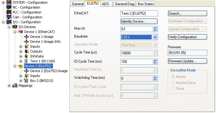 Fig.31: "EL6752" tab
EtherCAT
Terminal ID in the terminal network.
MAC-ID
Each DeviceNet® device - master included - requires a unique station number referred to as MAC ID (Medium Access Identifier) - value range: 0...63.
Baud rate
Baud rate setting: 125 kbaud, 250 kbaud or 500 kbaud
Cycle time
Displays the cycle time of the corresponding highest priority task. The display is updated when the mapping is generated.
IO-Cycle Time
Setting of the cycle time for the I/O connections. This value is the standard value for newly inserted boxes.
Watchdog time
Time until triggering of the watchdog
Search...
This function searches for all existing channels of the EL6752 and the desired one can be selected.
Check configuration
In preparation.
Firmware
Shows the current firmware version of the EL6752.
Firmware Update...
Updates the EL6752 firmware. Attention: The TwinCAT System must be stopped for this function.
“ADS” tab
 Fig.32: “ADS” tab
The EL6752 is an ADS device with its own net ID, which can be changed here. All ADS services (diagnostics, acyclical communication) associated with the EL6752 device must address the card via this NetID.
”Box States" tab
 Fig.33: "Box states" tab
Displays an overview of all current box statuses.
EL6752-0010 – DeviceNet® slave terminal
In the system configuration tree structure right-click on I/O Devices and “Append device” to open the selection list of supported fieldbus cards.
Select EL6752-0010 CANopenSlave. TwinCAT searches for the terminal and displays the memory addresses and slots it finds. Select the required address and confirm.
 Fig.34: Appending the device "DeviceNet slave EL6752, EtherCAT"
Right-click on "Device (EL6752-0010)" to insert the box for the EL6752-0010:
 Fig.35: Appending the box "DeviceNet slave EL6752, EtherCAT"
Selecting the I/O device for the EL6752-0010 in the tree structure opens a dialog with various configuration options:
“EL6752-0010” tab
 Fig.36: “EL6752-0010” tab
EtherCAT
Terminal ID in the terminal network.
MAC-ID
Each DeviceNet® device requires a unique station number referred to as MAC ID (Medium Access Identifier) - value range: 0...63.
Baud rate
The baud rate is set here.
Cycle time
Displays the cycle time of the corresponding highest priority task. The display is updated when the mapping is generated. The network variables are updated with the cycle of this task.
Watchdog time
Time until the watchdog is triggered
Search...
Searches for all available EL6752-0010 channels, from which the required channel can be selected. In the case of an FC5102 both channels A and B appear. These behave in logical terms like two FC5101 cards.
Firmware
Displays the current EL6752-0010 firmware version.
Firmware Update...
Updates the EL6752-0010 firmware. Attention: The TwinCAT System must be stopped for this function.
“ADS” tab
 Fig.37: “ADS” tab
The EL6752-0010 is an ADS device with its own net ID, which can be changed here. All ADS services (diagnostics, acyclic communication) associated with the EL6752-0010 device must address the card via this NetID. Additional ADS Net IDs can be entered for addressing subordinate ADS devices (e.g. an additional fieldbus card in the same PC) via the card.
"(Online) DPRAM" tab
Read access to the DPRAM of the card is provided for diagnostic purposes.
Box EL6752-0010 slave
A box "EL6752-0010 (DeviceNet slave)" is created automatically. Further parameters have to be set:
Box EL6752-0010 tab:
 Fig.38: "General" tab, Box EL6752-0010
DeviceNet® IO modes
The EL6752-0010 supports the DeviceNet® modes cyclic polling, change of state / cyclic and bit strobe. The IO modes can be selected according to the DeviceNet® specification.
The DeviceNet® IO mode cyclic polling is the default selection for the EL6752-0010:
|
IO mode |
Input data length / bytes |
Output data length / bytes |
|---|---|---|
|
Polling |
0 - 255 |
0 - 255 |
|
Change of State |
0 - 255 |
0 - 255 |
|
Cyclic |
0 - 255 |
0 - 255 |
|
Bit strobe |
1 bit |
0-8 |
Polling / Change of State (COS) / Cyclic
The cyclic polling mode is characterized by cyclic polling of the IO data by the master. The change of state mode is characterized by event-oriented sending of IO data. In cyclic mode the IO data are sent cyclically based on the communication parameters configured by the master. Since the communication settings are specified through the master no further settings are possible. Further information on the modes can be found in section DeviceNet® Communication. The settings are identical for these modes.
The input and output data lengths are pre-initialized to 8 byte each:
 Fig.39: Pre-initialized input and output data lengths in polling mode
According to needs and the application, further input or output data can be appended by right-clicking (Fig. Adding further variables). Any data type can be selected:
 Fig.40: Adding further variables
The data length is converted to a byte stream according to the DeviceNet® specification and displayed in the tab for the corresponding connection:
 Fig.41: "Connection" tab showing connection type "Polling" and input and output parameters
 | Maximum output data length The maximum data length per data direction is 255 bytes. |
The indicated input and output data lengths must be configured for the corresponding DeviceNet® master.
Bit strobe
The IO mode bit strobe involves an 8-byte command from the master to the slaves. For each possible address/MAC ID (DeviceNet address space: 64) 1 bit of user data is allocated. The maximum length of the response message from the slave is 8 bytes. It is sent to the master immediately when the bit strobe command is received.
 Fig.42: Display of output parameters in the TwinCAT tree for connection type "Bit strobe"
 | Maximum output data length The maximum output data length is 8 bytes. The input data length is fixed. |
Since the communication settings are specified through the master no further settings are possible.