Basic function principles
The EL6720 Lightbus master terminal is based on the characteristics of the FC2001/FC2002 master cards. The fieldbus cards are installed in the PC and are controlled directly by TwinCAT. The EL6720, however, is operated via the EtherCAT fieldbus.
For the EL6720 please note:
- Max. 3 CDLs (communication description lists, logical communication channels, allocated to a particular cycle time/task)
Each CDL has a number; the higher the number, the higher the priority. The FC200x has 8 CDL, counted as 1...8, the EL6720 therefore has the 3 CDLs 8, 7 and 6. - Lightbus IOs at the EL6720 require 1 cycle more in terms of response time compared with Lightbus IOs at a FC200x, since the EtherCAT fieldbus has to be taken into account
- The handling on error differs from the FC200x, see Operation in the event of a Lightbus error
- See also Lightbus information in the FC200x documentation
- See also Lightbus information in the C1220 documentation
Basic information on diagnostics
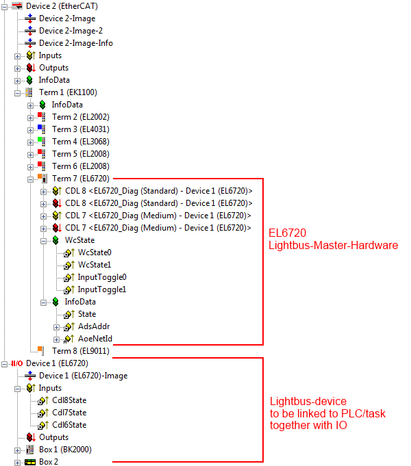
The following information is available for Lightbus diagnostics via the EL6720:
- Real-time diagnostics "cycle-current": Each Lightbus CDL has an
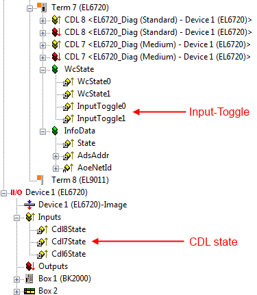
- InputToggle: toggles whenever new valid Lightbus telegram was received
- CDL state: if in this cycle invalid Lightbus data were received (e.g. incorrect checksum, attenuation too high, ...) or the transfer via the EtherCAT fieldbus failed, the CDLstate for this cycle is set to 1.
During normal operation the CDLstate is 0 -
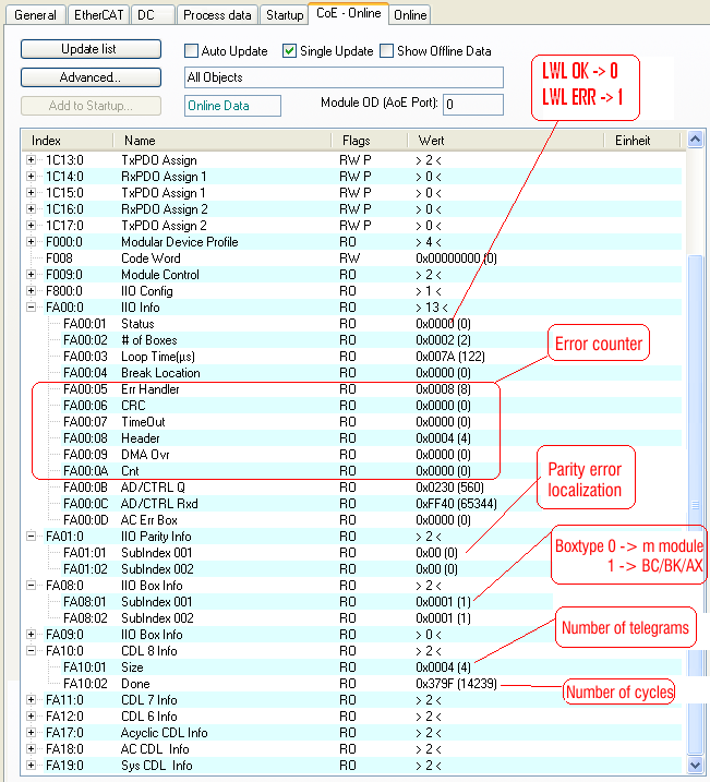
Acyclic information: A range of status information can be read from the CoE list of the EL6720.
The EL6720 Rev. 0017 has no offline dictionary, i.e. the CoE can only be viewed in online mode. Of particular interest are the objects 0xFA00 and 0xFA01. If a break in the optical fiber ring occurs, xFA00: 04 BreakLocation contains the number (1...) of the IO box after which the break occurred, for example (e.g. 2: interruption after box 2; 255: interruption point cannot be localized).
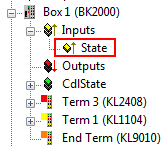
In addition it is advisable to diagnose the actual IO boxes, e.g. BK2000 coupler diagnosis in this example.
Operation in the event of a Lightbus error
If a Lightbus device fails or the Lightbus connection is interrupted, continuous communication is no longer possible. The Lightbus master where the line interruption can be found. Once the interruption has been rectified, the Lightbus master has to be restarted.
Recommended procedure in the event of a fault:
- Read the diagnostic information from the CoE list of the EL6720, e.g. from the PLC via ADS
See the diagnostics example program. (Download) - Repair or rectification of the fault
- The EL6720 is then in EtherCAT state SafeOp_Err and has to be reset:
- Clear Error
- Carry out the LowIntensityTest in the EL6720 (see CoE-overview xFA00:01 for any warnings)
- Set to OP
This can be done manually in the System Manager or, for example, from the PLC via FB_EcReqSlaveState from the TcEtherCAT.lib.
Optical fiber reset/attenuation test
The Lightbus route can be subjected to an attenuation test via the EL6720. This attenuation test takes place by sending selected test telegrams at 80% transmission power for all modules
- after the EL6720 is first switched on (PowerOn)
- in the Preop/SafeOp state transition if an optical fiber error had previously occurred (see above)
- after a Lightbus error reset (see above)
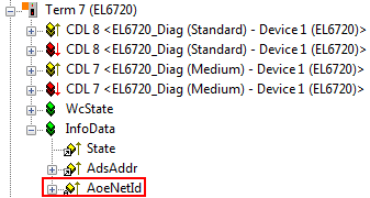
AoE
If ADS-capable devices are integrated in the Lightbus ring, they can be addressed in the chain TwinCAT --> EtherCAT --> EL6720 -> IO box (and back) with ADS and the ADS address. To enter the ADS route via the EL6720, the EL6720 offers the AoE address in the configuration:
Example program for Lightbus diagnostics
This example program  (Download)
illustrates how the PLC can read information from the EL6720 via the Lightbus mode. The reset process in the event of an error is also demonstrated. It is based on the data from the FC200x. The FB consolidates the data from EL6720/EtherCAT and DeviceLightbus to a diagnostic structure.
The analysis of the maximum number of CDL (3) is demonstrated by linking a PLC project with 3 tasks with cycle times of 1, 10 and 100 ms.