Basic principles of function and commissioning
The EL6692 is used for data exchange between two EtherCAT circuits. Predefined process data can be copied from one fieldbus side to the other. Status variables provide information about missing data and the status of the other side.
If distributed clocks are used in both EtherCAT circuits the EL6692 can also be used for synchronizing the two timebases. In this case the user has to define which side has the reference clock with the higher priority. The EL6692 will then send a reference clock correction value to the EtherCAT master with the lower priority.
Further information about operating principle and the application of distributed clocks can be found in the associated documentation at www.beckhoff.com.
The EL6692 consists of two EtherCAT slaves in one case: the EL6692 on the primary side (terminal bus) and the EL6692-0002 on the secondary side with network cable connection. Both slaves have their own power supplies and are thus independently operational. The primary side is supplied with 5 V via the E-bus, the secondary side with 24 V via the external connection.
Data transfer in the EL6692 is handled by a microcontroller that exchanges data in both directions in free-running mode. The transfer time from one side to the other depends on the number of bytes. The configurable "DC synchronous" mode does not apply to the process data exchange, but to the application of the EL6692 for distributed clock synchronization. The EL6692 does not deal with throughput control, i.e. the user has to ensure (through suitable programming) that the EL6692 is not supplied with more data than it can process, e.g. by using a higher-level handshake. The limit values specified below must be complied with.
The EL6692 supports EoE, Ethernet over EtherCAT. The means that not only cyclical process data can be transported from the EtherCAT side to the other side, but also standard Ethernet frames arriving at the EL6692 via mailbox communication. Since TwinCAT and the connected EtherCAT environment act as a virtual network card, Windows handles the routing of IP frames (e.g. 192.168.2.1) to the EL6692, in order to transport the frames to the EtherCAT system on the other side. Further information can be found in the EL6601/EL6614 documentation. No special EL6692 configuration is required.
 | EL6692 support in Beckhoff TwinCAT Full support for distributed clocks synchronization with the EL6692 is provided from TwinCAT version 2.11 or higher. Previous versions are limited to process data exchange. |
Application notes for EL6692, primary side
The default state of the EL6692 after reading/creation is
- DC support off - FreeRun
- No process data variables preconfigured
- No distributed clocks information data; see Process Data tab in the fig. Default process image for EL6692.
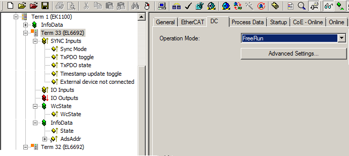 Fig.138: Default process image for EL6692
The process data to be transferred must now be created on the primary side as required. A right-click on "IO Inputs" or "IO Outputs" opens the dialog box from the fig. Appending process data variables.
 Fig.139: Appending process data variables
In the full configuration with activated PDO 0x1A02, the EL6692 provides the diagnostic process data from the fig. Full range of diagnostic process data
 Fig.140: Full range of diagnostic process data
- SyncMode: Information about the synchronization state. 0 = no synchronization, 1 = secondary side is Sync master, 2 = primary side is Sync master.
- TxPDO toggle: Bit toggles when a new set of process data has been delivered by the opposite side, but has not yet been collected by the receiving side. In this way the EL6692 also enables operation with EtherCAT cycle times that are greater than the transport time.
- TxPDO state: >0 if the other side is not in OP state.
- Timestamp update toggle: Bit toggles when new DC data were supplied.
- External device not connected: 1 = other side is not connected to its EtherCAT fieldbus.
- Internal time stamp: Distributed clocks time on the current side (primary or secondary)
- External time stamp: Distributed clocks time on the other side (primary or secondary).
- Control Value for DC Master Clock: Offset for correction of the lower priority reference clock.
Application notes for EL6692-0002, secondary side
The default state of the EL6692 after reading/creation is
 Fig.141: Default process image for EL6692-0002
In full configuration the EL6692-0002 offers the following variables:
 Fig.142: Full range of diagnostic process data
 - SyncMode: Information about the synchronization state. 0 = no synchronization, 1 = secondary side is Sync master, 2 = primary side is Sync master.
- TxPDO toggle: Bit toggles when a new set of process data has been delivered by the opposite side, but has not yet been collected by the receiving side. In this way the EL6692 also enables operation with EtherCAT cycle times that are greater than the transport time.
- TxPDO state: >0 if the other side is not in OP state.
- Control Value update toggle: Bit toggles when a new control value is available.
- Timestamp update toggle: Bit toggles when new DC data were supplied.
- External device not connected: 1 = other side is not connected to its EtherCAT fieldbus.
- Internal time stamp: Distributed clocks time on the current side (primary or secondary)
- External time stamp: Distributed clocks time on the other side (primary or secondary).
- Control Value for DC Master Clock: Offset for correction of the lower priority reference clock.
Process data declaration on the secondary side
Exactly as on the primary side (see the fig. Appending process data variables), the process data can be created manually on the secondary side also. The order and bit size on the secondary side must match those defined on the primary side.
Alternatively, from TwinCAT 2.10 build 1329 the configuration for the primary side can be loaded into the EL6692 and read on the secondary side. Corresponding support is necessary in the TwinCAT system manager for this and both EtherCAT sides must be accessible online. This avoids the manual configuration of the secondary side; see the fig. "Create configuration" on the primary side and "Get configuration" on the secondary side.
| Process data declaration in older TwinCAT 2.10 versions
Build 1325 to Build 1329: |
The procedure is as follows:
- Define the desired process data on the primary side, see the fig. Appending process data variables.
Notes: - max. 480 bytes in each data direction.
- no structures, only standard data types are allowed.
- Execute "Create Configuration" on the primary side – the table is created; see the fig. "Create configuration" on the primary side.
- Carry out a reload on the primary side or restart the configuration in Config mode. In order to apply the defined process data to the secondary side, both sides have to pass from the INIT state to the PREOP state.
 Fig.143: Device Reload
The error message "Invalid SM In cfg" or "Invalid SM Out cfg" appears in the logger window.
The secondary side can be read, if both EtherCAT sides of the EL6692 are at least in PRE-OP state.
- Execute "Get configuration" on the secondary side; see the fig. "Get configuration" on the secondary side. The process data configured on the primary side are generated accordingly in the configuration tree.
 Fig.144: "Create configuration" on the primary side
 Fig.145: "Get configuration" on the secondary side
The CoE folders of both halves of the EL6692 are used to save the process data configuration in the EL6692. The types and complexity of the definable process data are therefore limited. If the notes from the fig. "Get configuration" on the secondary side are displayed during the "Create Configuration" procedure, the secondary side must be checked for correct transmission of the configuration. The primary configuration may need to be changed if the note shown in the fig. Warning messages for complex data types appears during "Get Configuration".
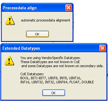 Fig.146: Warning messages for complex data types
 Fig.147: Warning message for complex data types
Application notes
Process data
The following must be observed in relation to the EL6692 process data:
-
Data quantity
a maximum of 480 bytes can be transmitted in each direction. -
Number of variables
no more than 59 variables should be configured per side (primary/secondary) and data direction (input/output). In total, 236 variables (4 * 59) can be cyclically transmitted. -
Alignment
The order of the variables of both data sides must be the same. In addition, 2-byte alignment must be complied with. This is automatically created with Create/GetConfiguration.
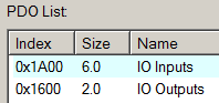 Fig.148: Correct 2-byte alignment of the PDO list
Diagnostics
Message
 Fig.149: Error message during bootup – General parameter incompatibility reason
Solution
Variable alignment not complied with, secondary side doesn't match primary side
→ transmit the variable configuration online to the secondary side using Create/GetConfiguration
Message
 Fig.150: Error message during bootup – Data type does not match, length of service parameter does not match, download pdo entries
Solution
more than 59 variables created, ADS logger message during bootup, data transmission in OP state may be possible
→ use fewer variables OR
→ do not download the PDO configuration (then up to 255 variables are possible without error message, but this should not be used)
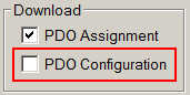 Fig.151: Deactivate PDO configuration download
Operation without primary side
The central controller of the EL669x is supplied with power from the primary side. If the EL669x is started from the secondary side without primary voltage, the secondary side is therefore unable to change from the INIT state. Similarly, if both sides were in operation, after a power failure on the primary side a regular status change is no longer possible on the secondary side. The secondary side responds to associated requests with ERROR.
For an automatic restart of the secondary bridge side, function blocks from the TcEtherCAT.lib should be used in the secondary-side PLC in this case. The default settings of the system manager "ReInit after ComError" and "Auto Restore States" are insufficient in this case.
The LED RUN SEC responds accordingly.
Operation mode
The EL6692-0002 can be operated with or without distributed clocks support. If no DC synchronization is required DC support can be switched off and the terminal can be operated in FreeRun mode. In this case the corresponding diagnostic process data are irrelevant. If DC support is desired, it must be activated on the primary and secondary side; see the fig. Mode switching. The operating mode "DC synchronous" only affects the operation of the EL6692 with distributed clocks synchronization.
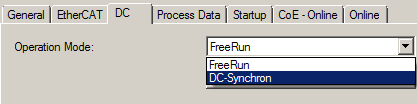 Fig.152: Mode switching
 | Support for distributed clocks with EL6692 in Beckhoff TwinCAT Full support for distributed clocks synchronization with the EL6692 is provided from TwinCAT version 2.10 build 1340 or higher. Previous versions are limited to process data exchange. |
Data transfer through the EL6692
Transporting the configured process data from one EtherCAT side to the other takes a certain amount of time, depending on the number of bytes. The data transfer is free-running and therefore not synchronized with one of the two EtherCAT sides. As a typical sample, measurement of an EL6692 with FW01 shows the following values:
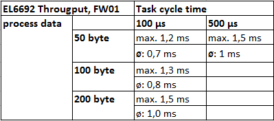 Fig.153: Typical throughput time measurement for a EL6692 (FW01) - Beckhoff reserves the right to modifications without notification.
The user is responsible for ensuring (via the diagnostic variables available for the EL6692 or a higher-level handshake) that data overload of the EL6692 is avoided with small EtherCAT cycle times (i.e. the quantity of data supplied to the device must not exceed the quantity the device can transport to the other side).
Link with process data SyncMode
The "SyncMode" status process data has 2 bits. IEC61131-PLC contains no data type that can be linked with this process data directly. This data was nevertheless chosen deliberately for reasons of data transfer efficiency.
An input variable of the type Byte must be defined in the task/program for linking; see the fig. Definition of byte process data.
 Fig.154: Byte process data definition
After double-clicking on SyncMode in the system manager, the dialog box from the fig. Definition of a variable of type Byte for linking opens.
 Fig.155: Definition of a variable of type Byte for linking
Select "All Types" to make Var109 available for selection. Otherwise only exactly matching 2 bit process data would be displayed. Now a dialog box opens for the specification of the offset; see the fig. Offset specification. Confirm the suggestion.
 Fig.156: Offset specification
Extent of process data
The EL6692 can transport a maximum of 480 bytes in each direction. In each transport direction the data may consist of a single large process data such as a structure or an array.
Declaration of bit process data
In the IEC61131-PLC a bit process data is only created on a bit address if it was defined "alone".
 Fig.157: Bit value declaration
In Fig. Bit values declaration "bBit 1" and "bBit2" are created as individual bit process data and interpreted as such in the link dialog of the System Manager. The abBitArray array consisting of 10 bits is created as 10 bytes, since the IEC61131-PLC is unable to handle an array consisting of individual bits.
The same applies to bit variables in structures (in IEC61131-PLC).