Inputs
EL5101-00xx input impedance
The signal source must be able to operate the input impedance of the EL5101-00xx (typically 220 Ω, subject to modification) with adequate voltage levels according to RS422.
Notice | |
Fast digital inputs – interference from interfering devices Please note that the input wiring has very little filtering. It has been optimized for fast signal transmission from the input to the evaluation unit. In other words, rapid level changes/pulses in the µs range and/or high-frequency interference signals from devices (e.g. proportional valves, stepper motor or DC motor output stages) arrive at the evaluation unit almost unfiltered/unattenuated. These interferences can be incorrectly detected as a signal.
|
Gate and latch input (EL5101-00x0)
For gate and latch inputs (24 V) a max. input frequency of 1 MHz is permitted (Subject to modification).
Both inputs are type 3 inputs according to EN 61131-2, with a minimum pulse duration of tON > 1µs.
Digital input type 3, according to EN 61131-2 | Voltage [V] | Input current [mA] |
|---|---|---|
Signal voltage "0 - LOW" | -3 V ... +5 V typ. | 0 mA ... 2.6 mA typ. |
Signal voltage "1 - HIGH" | 11 V ... 30 V typ. | typ. 3 mA |
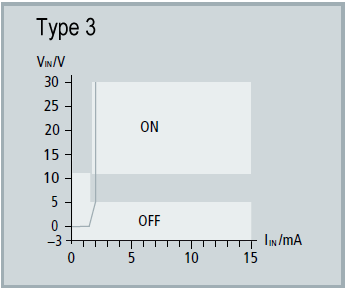 Fig.9: Characteristic 24 VDC Input type 3
Status input (EL5101-00x0)
The terminal provides a Status Input. The alarm output or status output of an encoder can be connected to this input.
The input is 5 V compatible.
Digital input, | Voltage [V] | Input current [mA] |
|---|---|---|
Signal voltage "0 - LOW" | 0 V … + 0.8 V | typ. < 1 mA |
Signal voltage "1 - HIGH" | +2 V … +5 V | typ. 0 mA |
Notice | |
Wiring of the Status Input In the terminal the Status Input is internally connected to 5 V via a pull-up resistor. The alarm output or status output of the encoder is usually designed with negative logic. This means that contacting against GND leads to an error bit and the LED display. External power supply is not recommended. If an external supply is used, the maximum permitted voltage is 5 V against GND. |