EL5101-0011 - LEDs and Connection
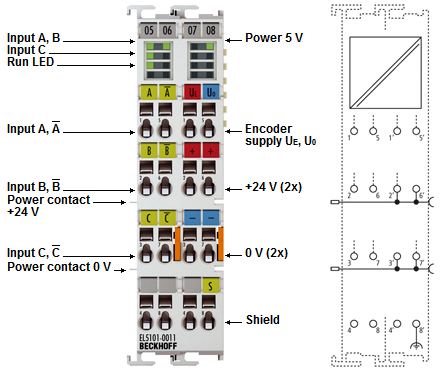 Fig.6: EL5101-0011
Notice | |
Encoder supply via the terminal The encoder supply voltage, can be taken from the terminal points 1’(5 V) and 5`(0 V). |
Notice | |
Single-ended connection for TTL encoder For information on the single-ended connection for TTL encoders, please refer to chapter "Single-Ended Connection for TTL Encoders ("Normal Operating Mode" or "Enhanced Operating Mode").
|
Connection | ||
|---|---|---|
Terminal point | No. | Comment |
A | 1 | Encoder input A |
B | 2 | Encoder input B |
C | 3 | Encoder input C |
- | 4 | - |
¬A | 5 | Encoder input A |
¬B | 6 | Encoder input B |
¬C | 7 | Encoder input C |
- | 8 | - |
Ue = +5 V | 1' | +5 V encoder supply |
+24 V | 2' | +24 V (internally connected to terminal point 6' and positive power contact) |
0 V | 3' | 0 V (internally connected to terminal point 7' and negative power contact) |
- | 4' | - |
Uo = 0 V | 5' | 0 V encoder supply |
+24 V | 6' | +24 V (internally connected to terminal point 2' and positive power contact) |
0 V | 7' | 0 V (internally connected to terminal point 3' and negative power contact) |
Shield | 8' | Shield |
LEDs
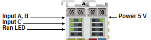 Fig.38: EL5101-0011 - LEDs
LED | Color | Meaning | |
|---|---|---|---|
INPUT A, B, C | green | indicates TRUE level | |
RUN | green | This LED indicates the terminal's operating state: | |
off | State of the EtherCAT State Machine: INIT = initialization of the terminal or BOOTSTRAP = function for firmware updates of the terminal | ||
flashing | State of the EtherCAT State Machine: PREOP = function for mailbox communication and different standard-settings set | ||
Single flash | State of the EtherCAT State Machine: SAFEOP = verification of the Sync Manager channels and the distributed clocks. | ||
on | State of the EtherCAT State Machine: OP = normal operating state; mailbox and process data communication is possible | ||
POWER 5 V | green | Operating voltage display for incremental encoder power supply | |