Features CoE
Notice | ||
 | Parameterization via the CoE list (CAN over EtherCAT) The EtherCAT device is parameterized via the CoE - Online tab (with a double click on the respective object) or via the Process Data tab (assignment of PDOs). A detailed description can be found in the EtherCAT System-Documentation in chapter “EtherCAT subscriber configuration” Please note the general CoE notes in the EtherCAT System Documentation in chapter “CoE-interface” when using/manipulating the CoE parameters: | |
Depending on the main PDO/optional PDOs further settings can be selected in the CoE list (CAN over EtherCAT).
The following CoE settings are possible from object 0x8000 and are shown below in their default settings:
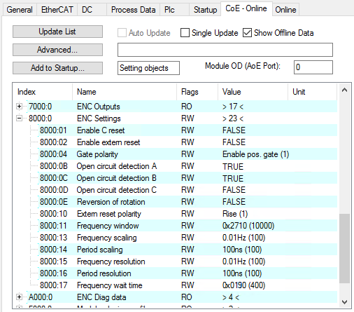 Fig.53: “CoE online” tab
The parameters are described on page “Object description and parameterization”.
Frequency
- The time window for the frequency calculation and the resolution can be parameterized in CoE objects 0x8000:11, 0x8000:13, 0x8000:15, 0x8000:17.
- The positive edges of track A are counted within the specified timeframe and the next edge including the time up to it are counted. The waiting time can be set in CoE object 0x8000:17 “Frequency Wait Time” (unit: ms). The default value is 1.6 sec. This is also the maximum value.
- The time window is 10 ms (default), min. 1 µs. With the default setting it is possible to measure frequencies up to approx. 800 kHz. At higher frequencies a smaller value must be selected for the timeframe.
- The time is measured with a resolution of 100 ns.
- This calculation is carried out in the slave without reference to the distributed clocks system. It is therefore independent of the DC mode.
- No frequency measurement is possible if the counter is blocked by the gate. In this case the period can be measured regardless.
- A C or external reset restarts the frequency measurement. The last frequency value remains unchanged until a new frequency value is determined.
Frequency measurement
- Basic unit 1 µs: all window sizes
Measurement sequence
- The measurement starts with a positive edge at track A. The current counter value and time (resolution: 100 ns) are stored.
- After the measuring window time has elapsed (index 0x8000:11), the system waits for the following rising edge at track A or a maximum of 1.6 sec or the time from 0x8000:17
- The frequency is calculated from the edge difference and the actual elapsed time.
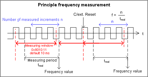 Fig.46: Frequency measurement principle in enhanced operation mode
Period calculation
- This calculation is carried out in the slave without reference to the distributed clocks system. It is therefore independent of the DC mode.
- In each cycle the interval between two positive edges of input A is counted with a resolution of 100 ns.
- If no edge change occurs for approx. 1.6 s, any period specification is cancelled.
 | Frequency and period measurement From the explanatory notes above it is apparent that the frequency measurement can measure the current axis status (velocity) significantly more accurately than the period measurement. Frequency measurement is therefore preferable, if possible. |
Latch
- Activating the latch C input (C) and latching the counter value
- Upon the first external latch pulse (positive edge at input C) after a bit has been set in the output process data “Enable latch C” = TRUE (index 0x7000:01), the counter value is saved (this takes precedence over process data “Enable latch extern on positive/negative edge“ (index 0x7000:02/0x7000:04)). When this bit is set, the following pulses at the other inputs have no effect on the latch value in the input process data “Latch value” (index 0x6000:12).
| “Latch C valid” bit Only when the value of the bit in the input process data “Latch C valid” (index 0x6000:01) is FALSE can a new counter value be written to the latch input. |
- Activating the external latch input (“gate/latch”) and latching the counter value
- If the bit in process data “Enable latch extern on positive edge” (index 0x7000:02) is set to TRUE, the counter value is stored in the latch input in process data “Latch value” (index 0x6000:12) upon the first external latch pulse with a rising edge. The subsequent pulses have no influence on the latch value in “Process data” (index: 0x6000:12).
- If the bit in the process data “Enable latch extern on negative edge” (index 0x7000:04) is set to TRUE, the counter value is stored at the latch input (index 0x6000:12) upon the first external latch pulse with a falling edge. The subsequent pulses have no influence on the latch value in “Process data” (index: 0x6000:12).
| “Latch extern valid” bit Only when the value of the bit in the input process data “Latch extern valid” (index 0x6000:02) is FALSE can a new counter value be written to the latch input. |
Reset
- Resetting the counter (index 0x8000:01, 0x8000:02, 0x8000:10): To reset the counter via input C, set the bit at index 0x8000:01; to reset it via the external latch input, set the bit at index 0x8000:02.
- The “Enable C reset” (0x8000:01) and “Enable external reset” (0x8000:02) functions cannot be enabled at the same time.
- Note: “Extern reset polarity” index 0x8000:10: Using the index 0x8000:10, you can select the edge to reset the counter to zero.
- Bit not set: Counter is set to Zero with falling edge.
- Bit set: Counter is set to Zero with rising edge.
Wire break detection “Open circuit detection”
- A separate wire break detection can be activated for each of the channels A, B, and C (index 0x8000:0B, 0x8000:0C, 0x8000:0D).
- Wire break detection is activated for channels A and B by default.
- A differential voltage in the range of typ. -0.475 V > Vid > +0.475 V is detected as a wire break.
- A detected wire break is indicated by the process data “Open circuit” (index 0x6000:07) = TRUE. A wire break is also indicated separately in indices 0xA000:01 (track A), 0xA000:02 (track B), and 0xA000:03 (track C).
- The input process data “TxPDO State” also becomes TRUE when a wire break is detected, since the data must be assumed to be invalid.