Incremental encoder basics
Incremental encoders divide a 360° rotation of the encoder axis into individual steps (increments) and mark a full revolution by means of a special mark (zero pulse). An RS422 encoder transmits the signal symmetrically as a differential line pair. TTL encoders use single signal lines (single-ended).
The terminal evaluates the 90° phase-shifted square wave signals of an incremental encoder on tracks A and B. The zero pulse is captured on track C. With a differential connection, the inverted signals (A̅, B̅, C̅) are also recorded.
These signals are converted by means of the quadrature decoder and counter into a position value with optional quadruple evaluation. The digital inputs enable latch, reset and set functionalities and thus exact and speed-independent referencing and storage of the counter value.
Encoder type | Incremental signals | |
|---|---|---|
RS422 encoder | with zero pulse | A, A̅, B, B̅, C, C̅ |
RS422 encoder | without zero pulse | A, A̅, B, B̅ |
RS422 counter or pulse generator | with zero pulse | A, A̅, C, C̅; |
RS422 counter or pulse generator | without zero pulse | A, A̅; |
TTL encoder | with zero pulse | A, B, C |
TTL encoder | without zero pulse | A, B |
TTL counter or pulse generator | with zero pulse | A, C; |
TTL counter or pulse generator | without zero pulse | A, |
The phase position between the signals on track A and track B determines the counting direction.
Forward (cw): Signal on track A leads track B by 90°
Reverse (ccw): Signal on track A lags track B by 90°.
With quadruple evaluation the rising and falling edges on track A and track B are counted.
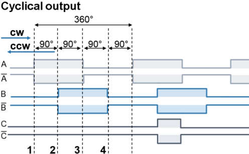 Fig.8: Incremental signals
Absolute value encoders provide an absolute position value directly after switch-on, which is unambiguous over the entire travel path. With incremental encoders, homing must be performed after switch-on in order to be able to determine an unambiguous position.
Referencing can be carried out, for example, with the aid of referencing cams or using the zero pulse of the encoder.
Notice | |
Differential and single-ended connection The RS422 signal transmits a differential voltage, which makes the signal less sensitive to interference compared to a single-ended signal.
|