LEDs and connection
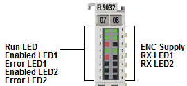 Fig.27: LEDs
Notice | |
Otherwise components may be damaged: Note encoder supply voltage! Note the limit values for the supply voltage specified in the data sheets of the encoder manufacturers. The encoder supply voltage may have to be adjusted in object 0x80p8:13 (5 V or 9 V)! |
LEDs
LED | Color | Meaning | |
|---|---|---|---|
RUN (1) | green | This LED indicates the terminal's operating state: | |
off | State of the EtherCAT State Machine: INIT = initialization of the terminal | ||
flashing | State of the EtherCAT State Machine: PREOP = function for mailbox communication and different standard-settings set | ||
single flash | State of the EtherCAT State Machine: SAFEOP = verification of the sync manager channels and the distributed clocks. Outputs remain in safe state | ||
on | State of the EtherCAT State Machine: OP = normal operating state; mailbox and process data communication is possible | ||
flickering | State of the EtherCAT State Machine: BOOTSTRAP = function for terminal firmware updates | ||
ENABLED 1 (2) | green | ON | Connected encoder for the corresponding channel initialized and ready for operation |
OFF | Connected encoder for the corresponding channel not ready for operation | ||
ERROR 1 (3) | red | ON | No encoder connected to the corresponding channel, or position values invalid (CRC error, not referenced, EnDat error bit set) |
FLASHES | Error during initialization (see diag history) | ||
OFF | No error | ||
ENC SUPPLY (9) | green | ON | Encoder voltage available |
OFF | 24 V field voltage missing or encoder voltage overload | ||
RX 1 (10) | green | FLASHES | Terminal receives position values at the corresponding channel |
Connection
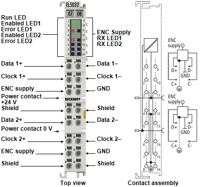 Fig.4: Connection
Notice | |
Encoder supply via the terminal The encoder supply voltage (5 V or 9 V), which can be set in object 0x80p8:13, can be taken from the terminal points 3 (channel 1) and 7 (channel 2). |
Terminal point | Description | |
|---|---|---|
Name | No. | |
Data 1+ | 1 | Data + input (channel 1) |
Clock 1+ | 2 | Clock + input (channel 1) |
ENC supply | 3 | Supply voltage for encoder (+5 V / +9 V) |
Shield | 4 | Shield |
Data 2+ | 5 | Data + input (channel 2) |
Clock 2+ | 6 | Clock + input (channel 2) |
ENC supply | 7 | Supply voltage for encoder (+5 V / +9 V) |
Shield | 8 | Shield |
Data 1- | 9 | Data - input (channel 1) |
Clock 1- | 10 | Clock - input (channel 1) |
GND | 11 | Ground |
Shield | 12 | Shield |
Data 2- | 13 | Data - input (channel 2) |
Clock 2- | 14 | Clock - input (channel 2) |
GND | 15 | Ground |
Shield | 16 | Shield |
 | Further connection information Further connection information can be found in the chapter "Technology". |