Commissioning instructions
Commissioning
Use indices 0x8000:06 to 0x8000:12 for setting the SSI bus data.
Default setting: 25 bits, no PowerFail bit.
Settings
 | Parameterization The terminal is parameterized via the CoE – Online tab (double-click on the respective object) or via the Process Data tab (assignment of PDOs). |
The EL5001-0011 settings are configured in the 0x8000 section of CoE.
| EtherCAT XML Device Description The display matches that of the CoE objects from the EtherCAT ESI Device Description (XML).We recommend downloading the latest XML file from the download area of the Beckhoff website and installing it according to installation instructions. |
| Parameterization via the CoE list (CAN over EtherCAT) The EtherCAT device is parameterized via the CoE-Online tab (double-click on the respective object) or via the Process Data tab (allocation of PDOs). Please note the following general CoE notes when using/manipulating the CoE parameters:
|
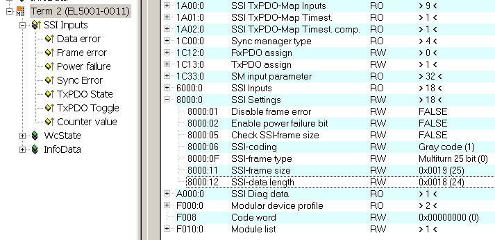 Fig.146: CoE settings and process data
SSI settings
- Index 0x8000:01, disable frame error
If the bit is set to TRUE, data errors such as invalid telegram size are no longer shown in the Data error process record. - Index 0x8000:02, enable power failure bit
If the bit is set to TRUE, the last bit in the telegram is interpreted as PowerFail bit and shown in the process data. - Index 0x8000:05, Check SSI frame size
The received telegram size is checked against the setting of index 0x8000:11/12 and shown in Data error if applicable - Index 0x8000:06, SSI-encoding
Dual or gray coding setting (standard). - Index 0x8000:0F, SSI-frame type
25, 13 or variable bit width (standard: 25). - Index 0x8000:11, SSI-frame size
Total data volume including PowerFail bit. - Index 0x8000:12, SSI-data length
Data volume without PowerFail bit
SSI communication sequence
The SSI master starts pulsing on the data line with a fixed cycle into the shift register of the SSI slave. The slave generally "pushes back" data with a width of 25 bits on the data line. An SSI encoder should determine its position with the first falling edge of the signal at the Clock input ("latching"), which is then transferred.
The last data bit can be a PowerFail bit, i.e. the slave signals a power failure.
The number of bit changes equals the clock frequency, i.e. the maximum data transfer rate for a 1 MHz cycle is 1 Mbit/s.
The EL5001-0011 cannot be operated with SingleEnded signals.
Distributed Clocks
An SSI encoder should determine its position at the first falling edge at the Data input after the pause ("latching"). If DC (distributed clock) is activated (-> DC tab), the EL5001-0011 stores this time and transfers it to the controller as a 32-bit or 64-bit value. To this end the corresponding process data must be activated in the ProcessData tab and TwinCAT must be restarted or EtherCAT reloaded (button  in the System Manager).
In the SyncManager 3 the 64-bit timestamp can be activated with index 0x1A01 and the 32-bit timestamp with index 0x1A02 (Fig. PDO change, switchover from 64-bit to 32-bit timestamp).
 Fig.147: PDO change, switchover from 64-bit to 32-bit timestamp
 | Latch time The EL5001-0011 can only determine the time at which the latch signal is present at the Data input. The time it takes for the encoder to latch its position depends on the encoder type. For further details please contact the encoder manufacturer. |
Process data
The SSI data are transferred to the controller via the 32-bit "CounterValue" process data.
"Data Error" may indicate:
- incorrect polarity: signal levels are incorrect during the pause time.
- incorrect telegram length.