Measurement SG 1/4 bridge (quarter bridge) 120 Ω 2/3-wire connection
To determine the measuring error:
The transition resistance values of the terminal contacts affect the measurement. The measuring error can be reduced further through compensation by the user, with active signal connection.
The temperature coefficient (Terminal) can be significantly improved through an external, more temperature-stable auxiliary resistor and the terminal in half/full bridge operation.
Quarter bridge calculation:
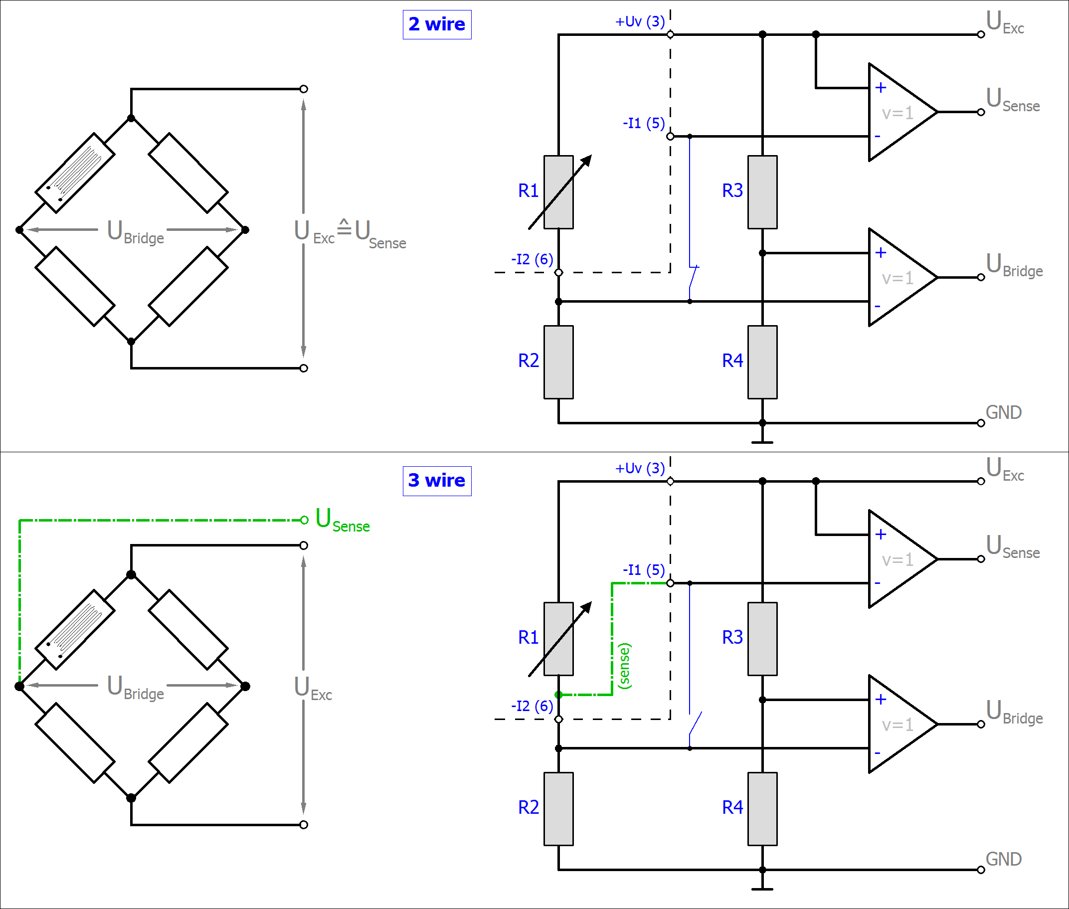
R2/3/4 are the internal switchable input resistors of the terminal.
The strain relationship (µStrain, µε) is as follows:
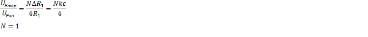
For the quarter bridge, N=1 always applies.
Note: specifications apply for 2.5 V SG excitation.
Measurement mode | SG 1/4 bridge 120 Ω | |
|---|---|---|
Measuring range, nominal | 120 ± 12 Ω or ±25 mV/V [corresponds to 108 Ω…132 Ω] [corresponds to ±50000 µε at K=2] | |
Measuring range, end value (full scale value) | 132 Ω | |
Measuring range, technically usable | 120 ± 12.88.. Ω | |
PDO resolution | 24 bit (including sign) | |
PDO LSB (Extended Range) | 1.536 µΩ/Step | |
PDO LSB (Legacy Range) | 1.430.. µΩ/Step | |
Basic accuracy: Measuring deviation at 23°C, with averaging (2 | 2-wire connection: 0.05% typ. (relative to full scale value) 3-wire connection: 0.04% typ. (relative to full scale value) 4-wire connection: not possible | |
Integrated power supply | 0.5…2.5 V adjustable, max. supply/excitation 21 mA (internal electronic overload protection) | |
Temperature coefficient (¹ | TcTerminal | <8 ppm/K typ. <12 ppm/K typ. (rel. to full scale value, HW Version 04, since production 2016 week 10; refer to serial number) <60 ppm/K typ. |
¹) Please see the remarks to 2/3/4 wire measurement within section for resistance measurement of section “technical data”.
2) Dominant part of the basic accuracy is its offset specification (see following tables). The process described in the Offset correction section eliminates this proportion and increases the measurement accuracy considerably.
Measurement mode | SG 1/4 bridge 120 Ω (2 wire) | ||||
|---|---|---|---|---|---|
Offset/Zero Point deviation (at 23°C) | EOffset | < 420 [ppmFSV] | |||
Gain/scale/amplification deviation (at 23°C) | EGain | < 250 [ppm] | |||
Non-linearity over the whole measuring range | ELin | < 50 [ppmFSV] | |||
Repeatability (at 23°C) | ERep | < 15 [ppmFSV] | |||
Noise (without filtering, at 23°C) | ENoise, PtP | < 160 [ppmFSV] | < 13750 [digits] | ||
ENoise, RMS | < 20 [ppmFSV] | < 1720 [digits] | |||
Max. SNR | > 73.1 [dB] | ||||
Noisedensity @1kHz | < 37.36 | ||||
Noise (with 50 Hz FIR filtering, at 23°C) | ENoise, PtP | < 6 [ppmFSV] | < 520 [digits] | ||
ENoise, RMS | < 1 [ppmFSV] | < 86 [digits] | |||
Max. SNR | > 99.2 [dB] | ||||
Common-mode rejection ratio (without filtering)3 | DC: | 50 Hz: | 1 kHz: | ||
Common-mode rejection ratio (with 50 Hz FIR filtering)3 | DC: | 50 Hz: | 1 kHz: | ||
Largest short-term deviation during a specified electrical interference test | ±1%FSV typ. | ||||

3) Values related to a common mode interference between SGND and internal ground.
Measurement mode | SG 1/4 bridge 120 Ω (3 wire) | ||||
|---|---|---|---|---|---|
Offset/Zero Point deviation (at 23°C) | EOffset | < 360 [ppmFSV] | |||
Gain/scale/amplification deviation (at 23°C) | EGain | < 150 [ppm] | |||
Non-linearity over the whole measuring range | ELin | < 50 [ppmFSV] | |||
Repeatability (at 23°C) | ERep | < 15 [ppmFSV] | |||
Noise (without filtering, at 23°C) | ENoise, PtP | < 160 [ppmFSV] | < 13750 [digits] | ||
ENoise, RMS | < 20 [ppmFSV] | < 1720 [digits] | |||
Max. SNR | > 73.1 [dB] | ||||
Noisedensity @1kHz | < 37.36 | ||||
Noise (with 50 Hz FIR filtering, at 23°C) | ENoise, PtP | < 6 [ppmFSV] | < 520 [digits] | ||
ENoise, RMS | < 1 [ppmFSV] | < 86 [digits] | |||
Max. SNR | > 99.2 [dB] | ||||
Common-mode rejection ratio (without filtering)3 | DC: | 50 Hz: | 1 kHz: | ||
Common-mode rejection ratio (with 50 Hz FIR filtering)3 | DC: | 50 Hz: | 1 kHz: | ||
Largest short-term deviation during a specified electrical interference test | ±1%FSV typ. | ||||
3) Values related to a common mode interference between SGND and internal ground.
The channel value (PDO) can be interpolated in ±12 Ω or ±25 mV/V:
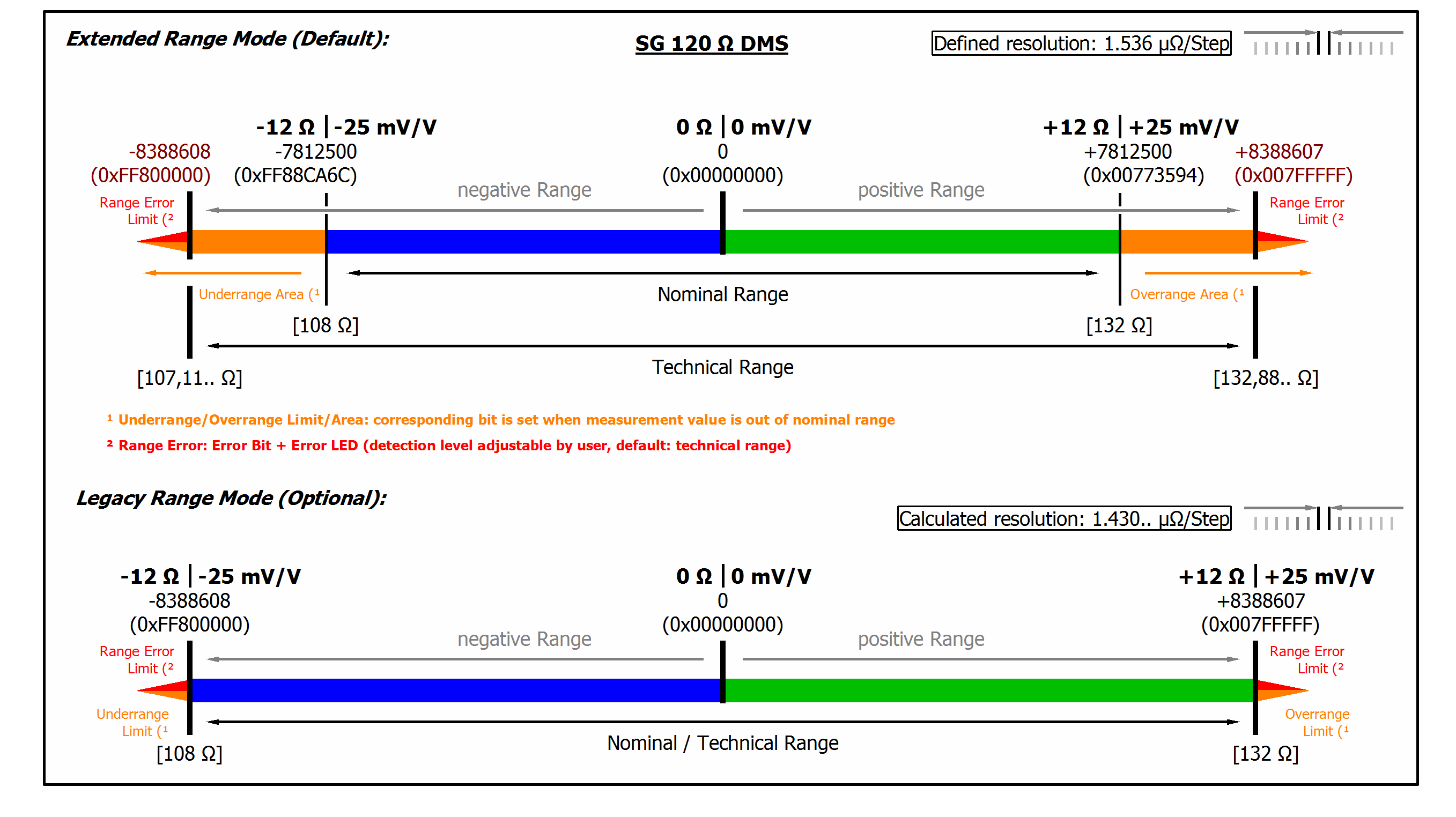 Fig.46: Representation measuring range SG 1/4 bridge 120 Ω