Most important CoE entries
|
Table of contents |
|---|
This chapter describes the CoE objects required for commissioning and user calibration.
 | Parameterization via the CoE list (CAN over EtherCAT) The terminal is parameterized via the CoE - Online tab (double-click on the respective object) or via the Process Data tab (allocation of PDOs). Please note the following general CoE information when using/manipulating the CoE parameters: |
Objects for commissioning
Index 1011 Restore default parameters
|
Index (hex) |
Name |
Meaning |
Data type |
Flags |
Default |
|---|---|---|---|---|---|
|
1011:0 |
Restore default parameters |
Restore default parameters |
UINT8 |
RO |
0x01 (1dez) |
|
1011:01 |
SubIndex 001 |
If this object is set to "0x64616F6C" in the set value dialog, all backup objects are reset to their delivery state. |
UINT32 |
RW |
0x00000000 (0dez) |
Index 80n0 SAI Settings (for Ch.1 (n=0); Ch.2 (n=1)
Index (hex) | Name | Meaning | Data type | Flags | Default |
|---|---|---|---|---|---|
80n0:0 | SAI Settings | Maximum subindex | UINT8 | RW | 0x3E (62dez) |
80n0:01 | Enable vendor calibration | Manufacturer calibration is active. | BOOLEAN | RW | 0x01 (1dec) |
80n0:02 | Enable user calibration | User calibration is active. | BOOLEAN | RW | 0x00 (0dec) |
80n0:05 | Enable delay time | The set delay time for this channel is active. | BOOLEAN | RW | 0x01 (1dec) |
80n0:09 | Disable Autorange | The Autorange function is disabled. | BOOLEAN | RW | 0x00 (0dec) |
80n0:0D | Mode | Measuring mode of the terminal: | Bit-Field[4] | RW | 0x00 (0dec) |
80n0:11 | Range | Measuring range: | INT8 | RW | 0x00 (0dec) |
80n0:1D | Presentation | 0: left-aligned | Bit-Field[4] | RW | 0x01 (1dec) |
80n0:21 | Filter Settings | Setting the hardware filter in ADC | UINT16 | RW | 0x02 (2dec) |
80n0:37 | Delay time | Delay time for this channel n*20 ms in the measuring ranges <1 MΩ, n*50 ms in the measuring range 7 (1 MΩ - 10 MΩ) | UINT8 | RW | 0x0A (10dec) |
80n0:3E | Steady state tolerance | If the last four values are no more than x / 1024 of end value apart, the "Steady state" bit is set to TRUE | UINT16 | RW | 0x0A (10dec) |
Objects for the user calibration
User calibration offers the option to process the value of the terminal further after manufacturer calibration. This can relieve the PLC.
Index 80n2 SAI User Data (for Ch.1 (n=0); Ch.2 (n=1)
|
Index (hex) |
Name |
Meaning |
Data type |
Flags |
Default |
|---|---|---|---|---|---|
|
80n2:0 |
SAI User Data |
Maximum subindex |
UINT8 |
RO |
0x24 (36dec) |
|
80n2:0m (odd) |
Range x 4 wire / 2 wire offset |
one offset value per measuring range for user calibration (see fig. below) |
UINT32 |
RW |
0x00000000 (0dec) |
|
80n2:0m (even) |
Range x 2/4W gain |
One gain value per measuring range for user calibration |
UINT32 |
RW |
0x10000 (65536dec) |
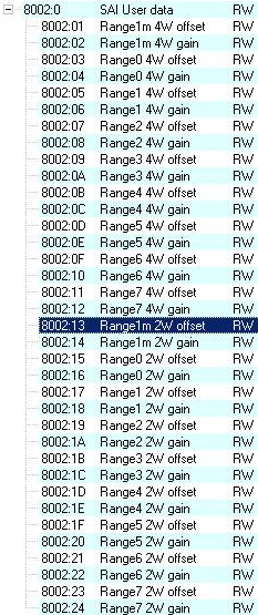 Fig.157: Offset value per measuring range for user calibration