Technology
The EL3692 resistance measuring terminal can measure resistances between milliohm (mΩ) and megohm (MΩ). 2- and 4-wire measurements are supported. The terminal is fully configurable via the Bus Coupler or the control system. Different output formats may be selected or own scaling activated.
Measuring principle of the terminal
The terminal actively applies a current to the test specimen. This current simultaneously flows through internal reference resistances. The actual resistance is determined from the proportion of the measured voltages. The terminal measures ratiometrically, i.e. fluctuations in the supply voltage and/or the measuring current have no influence on the accuracy.
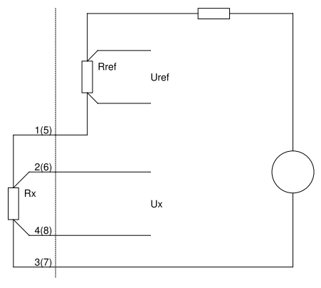 Fig.5: Principle of operation
The figure illustrates the following relationship between the known resistance Rref and the unknown resistance Rx:
Rx / Rref = Ux / Uref
Rx = Rref * Ux / Uref
The two channels of the EL3692 are measured alternately. To compensate capacitive processes the conversion time depends on the measuring range: the larger measuring range the longer the conversion. To measure a resistance at short intervals, the EL3692 should be used in single-channel mode. For measuring inductive/capacitive loads it should be noted that transition processes influence the result. A delay time can be specified in the channel settings in the CoE. The measurement and updating of the process data will only take place once this delay time (in [ms]) has elapsed (CoE 0x80n0:05 and :31). This delay time is particularly significant in Autorange mode: If it is too small, the measuring range may not change in Autorange mode because the respective measuring range limits are not reached. The automatic control in the EL3692 will try to optimize the waiting times, although manual adaptation may still be required.
The measuring frequency is determined from the filter setting for each channel. The lower the filter setting, the more measurements are carried out and averaged, and the more reliable is therefore the measurement.
The 9 measuring ranges each cover one decade. They each measure from 0 Ohm to 110% of full scale with their typical measuring current, see table. The measuring ranges of the two channels can be used independently of each other.
Although all measuring ranges theoretically measure down to 0 Ohm, the relatively large measuring error and the 2/4-wire connection technology must be taken into account with such small resistances. Apart from that, it will hardly be possible to achieve a "correct" zero measured value, because not even a connected (short) wire bridge has a resistance of 0 Ω.
In AutoRange mode, the measuring range used is determined by the terminal itself. For AutoRange operation, each measuring range can measure up to 110% above the respective measuring range end value. In this range, the measuring range is then switched to the next higher measuring range. Accordingly, below 10% of the measuring range, the changeover to the next smaller measuring range takes place. This method results in the following naming of the measuring ranges e.g. as "10..100 Ω", with 100Ω as measuring range end value and 10 Ω as lower threshold for the measuring range switchover.
In the manual mode, the measuring range is specified by the user via process data or CoE, in this case 0..110% of the respective measuring range can be measured.
The respective resistance is measured with 24 bit resolution (incl. sign). The measured value transmission takes place as 32 bit process date, in float (fixed point) or integer representation. Since no negative resistances can occur, the sign bit is used for the representation up to 110%
For more detailed information on settings and operating modes please refer to the sections on Process data, Operational characteristics, Diagnostics and Specific data.