Basic function principles
Measuring principle
The EL3443 works with 6 analog/digital converters for recording the current and voltage values of all 3 phases.
Recording and processing is synchronous and identical for the 3 phases. The signal processing for one phase is described below. This description applies correspondingly for all 3 phases.
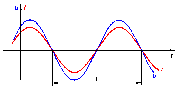 Fig.19: Voltage u and current i curves
RMS value calculation
The RMS value for voltage and current is calculated during the period T. The following equations are used:
u(t): instantaneous voltage value
i(t): instantaneous current value
n: number of measured values
The instantaneous values for current and voltage are low-pass filtered with a cut-off frequency of 2.5 kHz for the EL3443, EL3423 and EL3483.
Active power measurement
The EL34xx measures the active power P according to the following equation
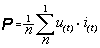
P: active power
n: number of samples
u(t): instantaneous voltage value
i(t): instantaneous current value
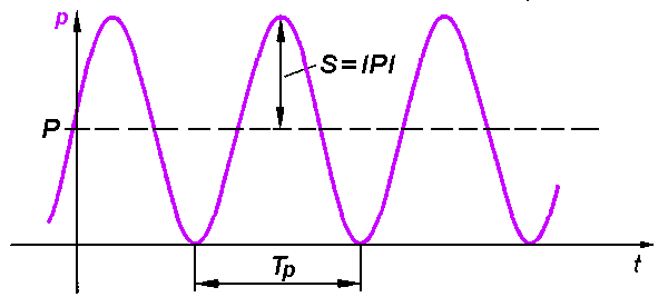 Fig.20: Power s(t) curve
In the first step, the power s(t) is calculated at each sampling instant:
The mean value is calculated over a period.
The power frequency is twice that of the corresponding voltages and currents.
Apparent power measurement
In real networks, not all consumers are purely ohmic. Phase shifts occur between current and voltage. This does not affect the methodology for determining the RMS values of voltage and current as described above.
The situation for the active power is different: Here, the product of RMS voltage and RMS current is the apparent power.
The active power is smaller than the apparent power.
S: apparent power
P: active power
Q: reactive power
φ: Phase shift angle
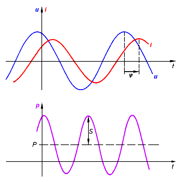 Fig.21: u, i, p curves with phase shift angle (t) (t) (t)
In this context, further parameters of the mains system and its consumers are significant:
- apparent power S
- reactive power Q
- power factor cos φ
The EL3443 determines the following values:
- RMS voltage U and RMS current I
- Active power P and active energy E
- Apparent power S and apparent energy
- Reactive power Q and reactive energy
- Power factor and cos(φ)
- Distortion factors for current THDI and voltage THDU
- Calculated RMS neutral conductor current IN
- Voltage imbalance
- Power quality factor (details see below)
- In "DC synchronous" mode, the distributed clock time of the voltage zero crossing is also available.
Sign for power measurement
The sign of the (fundamental wave) active power P and the power factor cos φ provides information about the direction of the energy flow. A positive sign indicates the motor mode, a negative sign indicates generator mode.
Furthermore, the sign of the fundamental harmonic reactive power Q provides information about the direction of the phase shift between current and voltage. Fig. Four-quadrant representation of active/fundamental harmonic reactive power in motor and generator mode illustrates this. In motor mode (quadrant I + IV), a positive fundamental harmonic reactive power indicates an inductive load, a negative fundamental harmonic reactive power indicates a capacitive load. The information about a capacitive or inductive load behavior is also shown in the sign of the phase angle φ, which is already contained in the EL3443.
In generator mode (quadrant II & III), an inductive generator is indicated by a positive fundamental harmonic reactive power, a capacitive generator by a negative fundamental harmonic reactive power.
Since the total reactive power is defined as the quadratic difference between apparent and active power, it has no sign. For the total active power, signs are permitted, as described above.
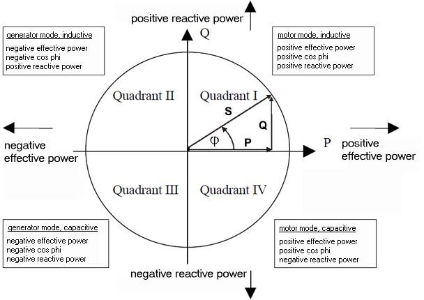 Fig.22: Four-quadrant representation of active power/fundamental harmonic reactive power in motor and generator mode
Frequency measurement
The EL34xx can measure the frequency for a voltage path input signal and a current path input signal. CoE objects "Reference" and "Frequency Source" (F800:11 and F800:13) can be used to set which frequency is to be output as PDO.
Power quality factor
The EL34xx calculates a PQF (power quality factor), which reflects the quality of the voltage supply as a simplified analog value between 1.0 and 0.
To calculate this factor, the measured values, frequency, RMS voltage, distortion factor and voltage imbalance are calculated and combined as shown in the following diagram.
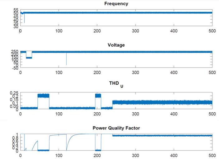 Fig.23: Representation of the power quality factor calculation
As can be seen for the time value 120, the calculation method is chosen in such a way that even very short voltage drops cause a clear signal deflection.
The value above which the power supply is to be regarded as "sufficiently good" is strongly dependent on the connected application. The more sensitive the application, the higher the minimum limit value of the PQF should be.
To adapt the power quality factor to your mains supply, enter the nominal voltage and frequency in CoE object "0xF801 PMX Total Settings PQF". This can also be done via the "Settings" tab, which summarizes all the important terminal setting options in a user-friendly manner.
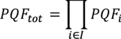
The other monitored parameters (distortion factor and voltage unbalance) each have three parameters xnenn, β, γ which are preset by the manufacturer. The combination of all factors is done by multiplication.
The corresponding filter equation
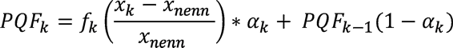
with

The factor αk thus contains the rate of change of the monitored variable. If xk changes significantly, αk also changes and the PQF reacts faster to changes.
In a real example, here using a short phase loss of 5 ms or 10 ms, the behavior of the PQF can be seen. For this example, the voltage (in green) was recorded at a frequency of 50 Hz using an EL3773. The PQF was calculated by an EL3483.
Example 1 shows a phase failure of 5 ms. This dropout can be seen on the PQF, but due to the length the factor does not go down to 0. The irregular dropout of the PQF over time can be explained by the calculation. The missing voltage increase is first visible in the voltage calculation (phase 1). In the second phase, the influence on the inertial calculation of the distortion also becomes clear.
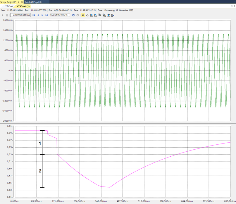 Fig.24: PQF at 5 ms phase loss
With a longer phase loss for 10 ms (example 2), the influence on the PQF can be seen even more clearly. When a half-wave fails, it can be clearly seen in the voltage calculation so that the PQF drops directly to 0.
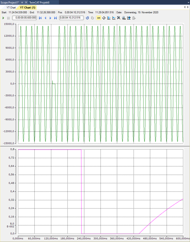 Fig.25: PQF at 10 ms phase loss
The voltage supply value to be regarded as "sufficiently good" depends to a large extent on the connected application. The more sensitive the application, the higher the minimum limit value of the PQF should be selected.
Voltage zero crossing
The EL3443 and EL3453 have the ability to determine the exact time of a voltage zero crossing. However, in order for this to be transmitted to a higher-level controller in a meaningful manner, the controller and the EtherCAT Terminal must have the same time base. Using distributed clocks technology, an EtherCAT system provides such a common time base (for details see EtherCAT system description). In order to be able to use these, the EL3443 must be in "DC synchronous" mode and the EtherCAT master must support the corresponding function.
Once these basic requirements have been met, the EL3443 and EL3453 provide the DC time of the penultimate zero crossing. In order to facilitate exact determination of the fundamental wave, the voltage signal to be evaluated must first be filtered, which inevitably entails a delay. In addition to the time of the voltage zero crossing, the EL3453 also determines the respective current zero crossings.
Statistical evaluation
In addition to the cyclic data, the EL34xx terminals also produce statistical evaluations over longer periods (can be set in the CoE: "F803 PMX Time Settings"). By default, the "F803:12 Measurement Interval" is set to 15 minutes. The clock available for this purpose in the terminal can not only be read out via the CoE object "F803:13 Actual System Time", it can also be actively influenced. Depending on the application, it may make sense to regularly synchronize the clock with an external clock. By default, the clock is set once at system startup based on the local Windows system time, taking into account the set time zone, usually UTC.
In addition, the interval can also be restarted manually via the "Reset Interval" output bit or directly from the application, for example to obtain statistics on a process that varies over time.
Notice | |
Increase of the rated voltage when grounding an outer conductor If an outer conductor is grounded (as is sometimes the case in the USA, for example), the rated voltage for dimensioning the application is increased to the phase-to-phase voltage. |
Calculation of the neutral current
Since the EL34xx terminals have direct access to the instantaneous current values of all three phases, the neutral current can be calculated or estimated, assuming that no current is lost to the system (in other words: the differential current is zero). The calculated (i.e. not measured) current value is output in index "F601:13 Calculated Neutral Line Current".
Since in the worst case all measurement errors add up, the maximum measurement error is correspondingly higher.
The additional possibility of measuring a fourth current value in the EL3453 means that either the differential current or the neutral current can be calculated. The other current can be measured directly using the fourth current channel. Due to the usual conditions and the corresponding measurement tolerances, however, it makes much more sense to measure the differential current with the aid of a summation current transformer and have the neutral conductor current calculated. Further information on this can be found in the chapter Application examples under the section Power measurement including residual current measurement.
Harmonic calculation
The EL34xx terminals perform an internal harmonic analysis for all current and voltage channels. For this purpose, a fundamental wave in the frequency range from 45 to 65 Hz is determined at the beginning (separately from the system frequency). The frequency value determined for the voltage harmonics can be read, for example, from index 99 (plus channel offset) of the variable output values and the amplitude in volts from index 98. The same applies to the current values - see "Variable output values".
The actual harmonic measured values are output as a percentage of the fundamental wave amplitude. It should also be noted that the zero harmonic indicates the DC component of the signal.