Settings
"Settings" Tab
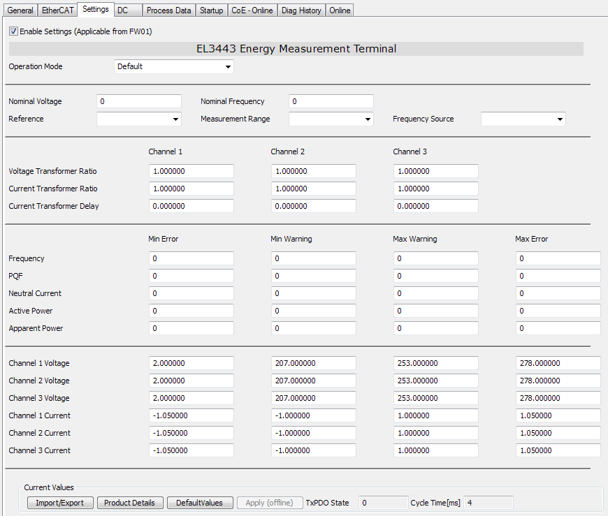 Fig.161: "Settings" tab
The "Settings" tab provides direct access to the most important configuration objects in the object data dictionary. It facilitates the terminal configuration.
The Import/Export button can be used to save and reload existing settings.
Using the EL3443 as a DPM current measurement terminal, shifting the start address Sync Manager
When using the terminal as a DPM current measurement terminal by activating the "DPM Data IN" PDO (0x1602), the start address of the last active Sync Manager must be shifted so that the object can be stored in the memory of the EtherCAT Slave Controller (ESC). Otherwise, the terminal will refuse to switch from the "PreOP" status to the "SafeOP" status.
First, the PDO Configuration must be selected by selecting the desired objects under the "Process Data" tab. If the object 0x1602 has been selected, the Sync Manager is adjusted under the "EtherCAT" tab. To do this, the corresponding screen (FMMU / SM) must be called up in the Advanced Settings.
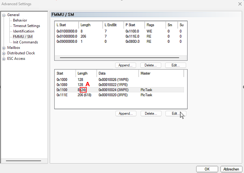 Fig.162: Shifting start address Sync Manager, tab "Advanced Settings", value "A": Length of the third SM
Now select the line of the third SYNC Manager and press the "Edit" button. In the following window, the start address is displayed in decimal form in the "Start Address" field ("B").
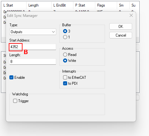 Fig.163: Decimal value of the start address of the third SM
The sum of the values "A" and "B" replaces the original start value of the last SYNC Manager, which is entered in the "Start Address" ("D") field by selecting the line and pressing the "Edit" button; in the example, this would be the value "4376dec"
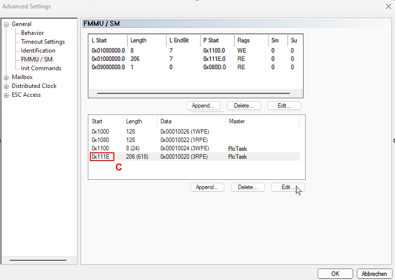 Fig.164: Replace the original start address "C" of the last SM
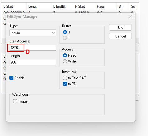 Fig.165: Enter the start address "D" of the last SM, sum of the values "A" and "B"
Confirmation of variable output values 1 - 4
(PDOs: PMX Variant Value In, Subindex "Index" [0xF60A:12, 0xF60A:14, 0xF60A:16, 0xF60A:18])
The calculated values can be output on the PDOs: PMX Variant Value In, Subindex "Variant value In" [0xF60A:12, 0xF60A:14, 0xF60A:16, 0xF60A:18].
To this end, the corresponding values for the measured value to be output should be entered in the PDOs: PMX Variant Value Out, Subindex "PMX Variant Value Out" [0xF700:11, 0xF700:12, 0xF700:13, 0xF700:14].
Assignment of variable output values plus channel offset (256 for channel 1; 512 for channel 2 or 768 for channel 3) | ||||
|---|---|---|---|---|
Values (dec), | Values (dec), | Meaning | Unit | Description |
1 (Examp.: 257 = 1 + 256 for ch. 1) | - | U RMS | V | RMS value of the voltage |
2 (Examp.: 770 = 2 + 768 for ch. 3) | - | U peak | V | Peak value of the instantaneous voltage in the last interval |
- | 3 | U Last Zero Cross | V | DC time of the penultimate voltage zero crossing |
4 | - | U RMS Minimum | V | Minimum RMS value of the voltage in the last interval |
5 | - | U RMS Maximum | V | Maximum RMS value of the voltage in the last interval |
6 | - | ULL | V | RMS value of the phase-to-phase voltage |
8 | - | I RMS | A | RMS value of the current |
9 | - | I peak | A | Peak value of the instantaneous current in the last interval |
- | 10* | I Last Zero Cross | ns | DC time of the last current zero crossing |
11 | - | I RMS Minimum | A | Minimum RMS value of the current in the last interval |
12 | - | I RMS Maximum | A | Maximum RMS value of the current in the last interval |
17 | - | Frequency | Hz | Frequency of this phase |
21 | - | Phi | ° | Phase angle of the fundamental wave |
22 | - | Cos phi | - | Cosine of the fundamental wave phase angle |
23 | - | Power Factor | - | Power factor |
26 | - | P | W | Active power |
27 | - | Pavg | W | Average active power during the last interval |
28 | - | Pmin | W | Minimum active power in the last interval |
29 | - | Pmax | W | Maximum active power in the last interval |
30* | - | Pfund | W | Fundamental wave active power in the last interval |
32 | - | S | VA | Apparent power |
33 | - | Savg | VA | Average apparent power during the last interval |
34 | - | Smin | VA | Minimum apparent power in last interval |
35 | - | Smax | VA | Minimum apparent power in last interval |
36* | - | Sfund | VA | Fundamental wave apparent power in the last interval |
38 | - | Q | var | Reactive power |
39 | - | Qavg | var | Average reactive power average during the last interval |
40 | - | Qmin | var | Minimum reactive power in the last interval |
41 | - | Qmax | var | Maximum reactive power in the last interval |
42* | - | Qfund | var | Fundamental wave reactive power in last interval |
- | 45 | EP | mWh | Recorded active energy |
- | 46 | EP pos | mhW | Received active energy |
- | 47 | EP neg | mWh | Supplied active energy |
- | 51 | ES | mWh | Apparent energy |
- | 57 | EQ | mWh | Reactive energy |
- | 63* | EP_fund | mWh | Balanced fundamental wave active energy |
- | 64* | EP pos_fund | mWh | Related fundamental wave active energy |
- | 65* | EP neg_fund | mWh | Input fundamental wave active energy |
- | 69* | ES _fund | mWh | Fundamental wave apparent energy |
- | 75* | EQ _fund | mWh | Balanced fundamental wave reactive energy |
- | 76* | EQ pos_fund | mWh | Inductive fundamental wave reactive energy |
- | 77* | EQ neg_fund | mWh | Capacitive fundamental wave reactive energy |
95 |
| THD_U | - | "Total Harmonic Distortion" is the distortion factor of the voltage. It indicates the ratio of the harmonic components of an oscillation relative to its fundamental. |
98 |
| RMS_fund_U | V | Amplitude of the fundamental wave |
99 |
| F_Ref_U | Hz | Reference frequency of the voltage harmonic: Specifies the underlying fundamental frequency, e.g.: 50 or 60 Hz. |
100-141 - 163* |
| Harmonics U 0 to 41 up to 63* | % of the fundamental wave | 0 => DC component 1 => fundamental wave 2=> 2nd harmonic 3=> 3rd harmonic |
165 |
| THD_I | - | "Total Harmonic Distortion" is the distortion factor of the current. It indicates the ratio of the harmonic components of an oscillation relative to its fundamental. |
166 |
| TDD_I | % of the maximum current | "Total Demand Distortion" indicates the ratio between the current harmonics and the maximum current (EL3443: 1A and EL3443-0010: 5A) |
168 |
| RMS_fund_I | A | Amplitude of the fundamental wave |
169 |
| F_Ref_I | Hz | Reference frequency of the current harmonic: Specifies the underlying fundamental frequency, e.g.: 50 or 60 Hz. |
170-211 - 233* |
| Harmonics I 0 to 41 up to 63* | % of the fundamental wave | 0 => DC component 1 => fundamental wave 2=> 2nd harmonic 3=> 3rd harmonic |
255 |
| Error: INDEX not valid | - | Error message: The selected index is not available. |
Values with star* are only available in the EL3453.
Assignment of variable output values across all channels | ||||
|---|---|---|---|---|
Values (dec), | Values (dec), | Meaning | Unit | Description |
1032 (= 1024 + 8) | - | In RMS | A | Calculated RMS value of the neutral current |
1033 (= 1024 + 9)* | - | In peak | A | Highest peak value of the instantaneous current in the last interval |
1035 (= 1024 + 11)* | - | In RMS Minimum | A | Smallest effective value of the current in the last interval |
1036 (= 1024 + 12)* | - | In RMS Maximum | A | Largest effective value of the current in the last interval |
1041 (= 1024 + 17)* | - | Frequency | Hz | Frequency of the PDO value set via CoE (see reference channel of frequency measurement) |
1047 (= 1024 + 23) | - | Power Factor | - | Total power factor over all phases |
1050 (= 1024 + 26) | - | Ptot | W | Total active power |
1051 (= 1024 + 27) | - | Ptotavg | W | Average total active power during the last interval |
1052 (= 1024 + 28) | - | Ptotmin | W | Minimum total active power in the last interval |
1053 (= 1024 + 29) | - | Ptotmax | W | Maximum total active power in the last interval |
1056 (= 1024 + 32) | - | Stot | VA | Total apparent power |
1057 (= 1024 + 33) | - | Stotavg | VA | Average total apparent power during the last interval |
1058 (= 1024 + 34) | - | Stotmin | VA | Minimum total apparent power in the last interval |
1059 (= 1024 + 35) | - | Stotmax | VA | Maximum total apparent power in the last interval |
1062 (= 1024 + 38) | - | Qtot | var | Total reactive power |
1063 (= 1024 + 39) | - | Qtotavg | var | Average total reactive power during the last interval |
1064 (= 1024 + 40) | - | Qtotmin | var | Minimum total reactive power in the last interval |
1065 (= 1024 + 41) | - | Qtotmax | var | Maximum total reactive power in the last interval |
- | 1069 (= 1024 + 45) | Eptot | mWh | Balanced total active energy |
- | 1070 (= 1024 + 46) | EPtot pos | mWh | Imported total active energy |
- | 1071 (= 1024 + 47) | EPtot neg | mWh | Generated total active energy |
- | 1072 (= 1024 + 48) | Eptot_intervall | mWh | Balanced total active energy in last interval |
- | 1073 (= 1024 + 49) | EPtot pos_intervall | mWh | Total active energy imported in the last interval |
- | 1074 (= 1024 + 50) | EPtot neg_intervall | mWh | Generated total active energy the last interval |
- | 1075 (= 1024 + 51) | EStot | mWh | Total apparent energy |
- | 1078 (= 1024 + 54) | EStot_intervall | mWh | Total apparent energy in the last interval |
- | 1081 (= 1024 + 57) | EQtot | mWh | Total reactive energy |
- | 1084 (= 1024 + 60) | EQtot_intervall | mWh | Total reactive energy in the last interval |
1094 (= 1024 + 70) | - | PhiL1L2 | ° | Phase shift angle between phase L1 and L2 |
1095 (= 1024 + 71) | - | PhiL1L3 | ° | Phase shift angle between phase L1 and L3 |
1096 (= 1024 + 72) | - | Unbalance | - | Ratio between negative and positive voltage system |
1104 (= 1024 + 80) | - | PQF | - | Power quality factor |
1105 (= 1024 + 81) | - | PQF Avg | - | Average value of the power quality factor during the last interval |
1106 (= 1024 + 82) | - | PQF Min | - | Minimum power quality factor in the last interval |
1107 (= 1024 + 83) | - | PQF Max | - | Maximum power quality factor in the last interval |
- | 1124 (= 1024 + 100)* | Eptot_fund | mWh | Balanced total fundamental wave active energy |
- | 1125 (= 1024 + 101)* | EPtot_fund pos | mWh | Received total fundamental wave active energy |
- | 1126 (= 1024 + 102)* | EPtot_fund neg | mWh | Supplied total fundamental wave active energy |
- | 1127 (= 1024 + 103)* | Eptot_fund _intervall | mWh | Balanced total fundamental wave active energy in the last interval |
- | 1128 (= 1024 + 104)* | EPtot_fund pos_intervall | mWh | Received total fundamental wave active energy in the last interval |
- | 1129 (= 1024 + 105)* | EPtot_fund neg_intervall | mWh | Supplied total fundamental wave active energy in the last interval |
- | 1130 (= 1024 + 106)* | EStot_fund | mWh | Total fundamental wave apparent energy |
- | 1133 (= 1024 + 109)* | EStot_fund _intervall | mWh | Total fundamental wave apparent energy in the last interval |
- | 1136 (= 1024 + 112)* | EQtot_fund | mWh | Balanced total fundamental wave reactive energy |
- | 1137 (= 1024 + 113)* | EQtot_fund pos | mWh | Inductive total fundamental wave reactive energy |
- | 1138 (= 1024 + 114)* | EQtot_fund neg | mWh | Capacitive total fundamental wave reactive energy |
- | 1139 (= 1024 + 115)* | EQtot_fund _intervall | mWh | Balanced total fundamental wave reactive energy in the last interval |
- | 1140 (= 1024 + 116)* | EQtot_fund pos_intervall | mWh | Inductive total fundamental wave reactive energy in the last interval |
- | 1141 (= 1024 + 117)* | EQtot_fund neg_intervall | mWh | Capacitive total fundamental wave reactive energy in the last interval |
1154 (= 1024 + 130)* | - | Ptot_fund | W | Total fundamental wave active power |
1155 (= 1024 + 131)* | - | Ptotavg_fund | W | Total fundamental wave average active power during last interval |
1156 (= 1024 + 132)* | - | Ptotmin_fund | W | Total fundamental wave minimum active power in the last interval |
1157 (= 1024 + 133)* | - | Ptotmax_fund | W | Total fundamental wave maximum active power in the last interval |
1160 (= 1024 + 136)* | - | Stot_fund | VA | Total fundamental wave apparent power |
1161 (= 1024 + 137)* | - | Stotavg_fund | VA | Total fundamental wave average apparent power during last interval |
1162 (= 1024 + 138)* | - | Stotmin_fund | VA | Total fundamental wave minimum apparent powerin the last interval |
1163 (= 1024 + 139)* | - | Stotmax_fund | VA | Total fundamental wave maximum apparent power in the last interval |
1166 (= 1024 + 142)* | - | Qtot_fund | var | Total fundamental wave reactive power |
1167 (= 1024 + 143)* | - | Qtotavg_fund | var | Total fundamental wave avarage reactive power during last interval |
1168 (= 1024 + 144)* | - | Qtotmin_fund | var | Total fundamental wave minimum reactive power during last interval |
1169 (= 1024 + 145)* | - | Qtotmax_fund | var | Total fundamental wave maximum reactive power during last interval |
Values with star* are only available in the EL3453.
Reference channel for the frequency measurement (index 0xF800:11 and index 0xF800:13)
The EL34xx can measure the frequency for a voltage path input signal and a current path input signal. CoE objects "Reference" and "Frequency Source" (F800:11 and F800:13) can be used to set which frequency is to be output as PDO.
Default: Voltage at channel 1
PT2 filter (EL3453)
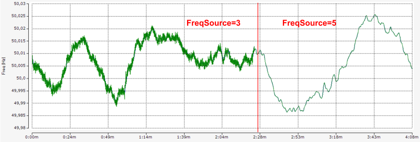 Fig.166: Setting Index F800:13; left without PT2 filter (FreqSource=3), right with PT2 filter (FreqSource=5)
Power quality factor setting
To adapt the power quality factor to your mains supply, enter the nominal voltage and frequency in CoE object "0xF801 PMX Total Settings PQF". This can also be done via the "Settings" tab, which summarizes all the important terminal setting options in a user-friendly manner.