EL3453-0090 – LED and connection
| |
Caution: Risk of injury through electric shock! If you do not connect the terminal point N with the neutral conductor of your mains supply (e.g. when using for current measurement only), terminal point N should be grounded, in order to avoid dangerous overvoltages in the event of a current transformer fault! |

| |
Caution: Risk of injury through electric shock! Please note that many vendors do not permit their current transformers to be operated in no-load mode! Connect the terminal to the secondary winding of the current transformers before using the current transformer! |
EL3453-0090 – LED and connection
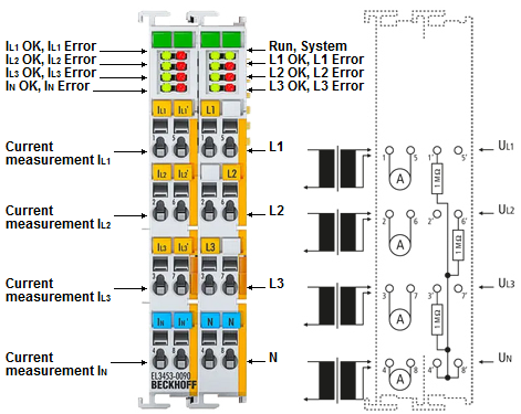 Fig.14: EL3453-0090, LED and connection (component values only examplary, for exact value see technical data)
Terminal point | Description | Comment | |
|---|---|---|---|
Name | No. | ||
IL1 | 1 | Phase L1 current measurement input | Connections for the current transformers. Note the warnings above - " Caution: Risk of electric shock! " |
IL2 | 2 | Phase L2 current measurement input | |
IL3 | 3 | Phase L3 current measurement input | |
IN | 4 | Neutral conductor current measurement input (star point) | |
IL1‘ | 5 | Phase L1 current measurement output | |
IL2‘ | 6 | Phase L2 current measurement output | |
IL3‘ | 7 | Phase L3 current measurement output | |
IN‘ | 8 | Neutral conductor current measurement output (star point) | |
L1 | 1‘ | Phase L1 | Connections for voltage measurement: |
| 2‘ | n.c. | |
L3 | 3‘ | Phase L3 | |
N | 4‘ | Neutral conductor N (internally connected with terminal point 8‘) | |
| 5‘ | n.c. | |
L2 | 6‘ | Phase L2 | |
| 7‘ | n.c. | |
N | 8‘ | Neutral conductor N (internally connected with terminal point 4‘) | |
LED | Color | Meaning | |
|---|---|---|---|
RUN | green | This LED indicates the terminal's operating state: | |
off | State of the EtherCAT State Machine: | ||
flashing rapidly | State of the EtherCAT State Machine: | ||
flashing | State of the EtherCAT State Machine: | ||
single flash | State of the EtherCAT State Machine: | ||
on | State of the EtherCAT State Machine: | ||
SystemOK | green | on | System OK, (the "SystemOK" LED is the image of the "System State" bit, F600:01) |
L1 - L3 | green | on | Right prism: |
flashes | Right prism: | ||
off | Right prism: | ||
L1 - L3 | red | on | |
IL1 - IL3 | green | on | Left prism: |
flashes | Left prism: | ||
off | Left prism: | ||
IL1 - IL3 | red | on | |
 L2
L2  L3
L3 
 L2
L2  L3
L3 
 L2
L2  L3
L3 
 IL2
IL2  IL3
IL3  IN
IN 
 IL2
IL2  IL3
IL3  IN
IN 
 IL2
IL2  IL3
IL3  IN
IN 