EL3413-0120
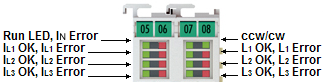
LEDs
LED | Color | Meaning | |
|---|---|---|---|
RUN | green | This LED indicates the terminal's operating state: | |
off | State of the EtherCAT State Machine: | ||
fast flashing | State of the EtherCAT State Machine: | ||
flashing | State of the EtherCAT State Machine: | ||
single flash | State of the EtherCAT State Machine: | ||
on | State of the EtherCAT State Machine: | ||
IN Error | red | on | Overcurrent on neutral (Current > 11 A) |
IL1 OK | green | on | Current IL1 ok |
IL1 Error | red | on | Overcurrent on L1. |
IL2 OK | green | on | Current IL2 ok |
IL2 Error | red | on | Overcurrent on L2. |
IL3 OK | green | on | Current IL3 ok |
IL3 Error | red | on | Overcurrent on L3. |
ccw | green | on | Counter-clockwise rotating field correctly detected |
cw | green | on | Clockwise rotating field correctly detected |
L1 OK | green | on | Voltage on L1 and zero crossing detected. Voltage > 5 V (L1-N) |
L1 Error | red | on | Over- or undervoltage on L1. Voltage < 5 V or voltage > 130 V (L1-N) |
L2 OK | green | on | Voltage on L2 and zero crossing detected. Voltage > 5 V (L2-N) |
L2 Error | red | on | Over- or undervoltage on L2. Voltage < 5 V or voltage > 130 V (L2-N) |
L3 OK | green | on | Voltage on L3 and zero crossing detected. Voltage > 5 V (L3-N) |
L3 Error | red | on | Over- or undervoltage on L3. Voltage < 5 V or voltage > 130 V (L3-N) |
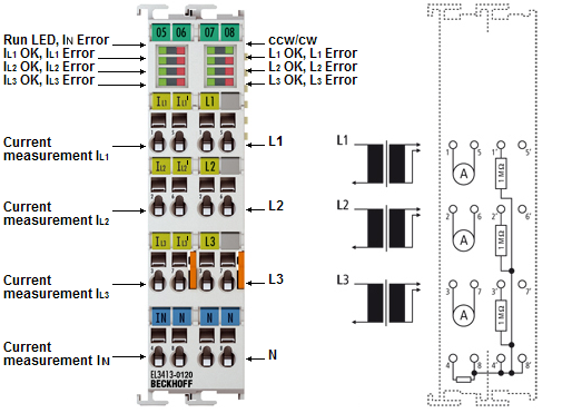
Connection
| |
Do not operate current transformers in no-load mode! Please note that many manufacturers do not permit their current transformers to be operated in no-load mode! Connect the EL3413 to the secondary windings of the current transformers before using the current transformer! |

|
Terminal point |
Description | |
|---|---|---|
|
Name |
No. | |
|
IL1 |
1 |
Phase L1 current measurement input |
|
IL2 |
2 |
Phase L2 current measurement input |
|
IL3 |
3 |
Phase L3 current measurement input |
|
IN |
4 |
Neutral conductor current measurement input (star point) |
|
IL1' |
5 |
Phase L1 current measurement output |
|
IL2' |
6 |
Phase L2 current measurement output |
|
IL3' |
7 |
Phase L3 current measurement output |
|
N |
8 |
Neutral conductor |
| |
Earthing of the terminal point N when measuring current! If you do not connect the terminal point N with the neutral conductor of your mains supply (e.g. if the terminal is used purely for current measurements) and use the IN current measurement channel, terminal point N should be earthed, in order to avoid dangerous overvoltages in the event of a current transformer fault. Earthing of the N point is not absolutely necessary if only the galvanically isolated current channels are used. |
|
Terminal point |
Description | |
|---|---|---|
|
Name |
No. | |
|
L1 |
1' |
Phase L1 voltage measurement input |
|
L2 |
2' |
Phase L2 voltage measurement input |
|
L3 |
3' |
Phase L3 voltage measurement input |
|
N |
4' |
Neutral conductor |
|
|
5' |
n.c. |
|
|
6' |
n.c. |
|
|
7' |
n.c. |
|
N |
8' |
Neutral conductor |