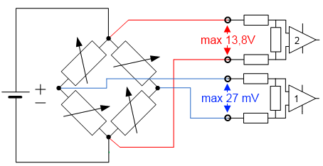
The measuring ranges of both channels (supply voltage and bridge voltage) should always be used as widely as possible in order to achieve a high measuring accuracy. We recommended a supply voltage of 12 V in connection with a load cell that has such a sensitivity (e.g. 2 mV/V) that the largest possible bridge voltage - ideally ±25 mV - is generated. Note the input voltages (see Technical data).
Max. input voltages
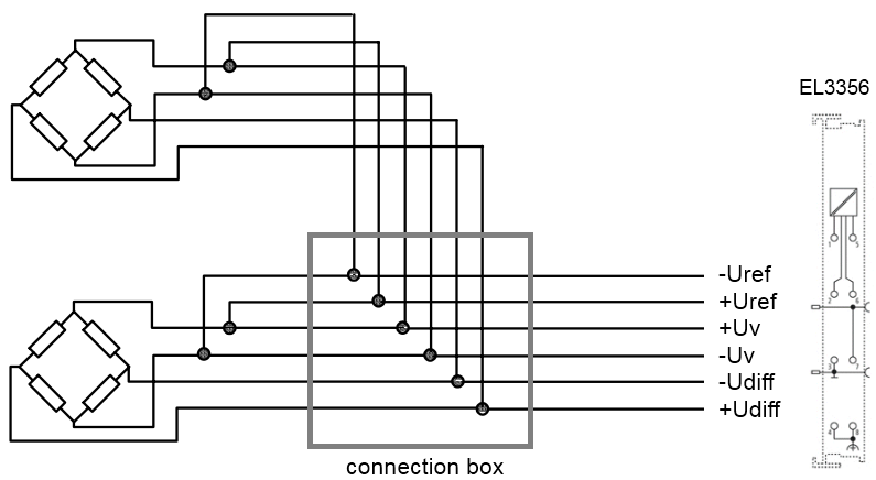
Parallel operation of load cells is possible with the EL3356. Please note:
the EL3356 does not provide a supply! Hence, the power supply employed must be sufficiently large, since the total bridge resistance of all strain gauges connected together is considerably reduced due to the parallel connection.
Load cells approved and calibrated by the load cell manufacturer for parallel operation should be used. The nominal characteristic values [mV/V], zero offset [mV/V] and impedance [Ω, ohm] are then usually adjusted accordingly.
a 6-wire connection is expressly recommended
Parallel connection with EL3356
Load cell signals have a low amplitude and are occasionally very sensitive to electromagnetic interference. Considering the typical system characteristics and taking into account the technical possibilities, purposeful state-of-the-art EMC protective measures are to be taken. The shield of the sensor cable can be connected to the EL3356 at the terminal points 4/8. In the case of high electromagnetic interference levels, it may be helpful to additionally connect the cable screen before the terminal using suitable screening material.
The minimum permissible assigned EtherCAT cycle time for the EL3356 is 100 µs.
If the EL3356-0010 and EL3356-0090 are to be used in Distributed Clocks mode - DC must be activated - the timestamp process record must be activated. In this case, the filter functions are inactive.