Description of the example program
The following list provides an overview of the abbreviations used in the further course of the description:
|
Power supply terminal |
Input voltage |
Output voltage |
Output current |
|---|---|---|---|
|
UDiff |
24 VDC |
5 VDC ±1% |
0.5 A |
|
URef |
24 VDC |
8 VDC ±1% |
0.5 A |
|
Emax |
24 VDC |
10 VDC ±1% |
0.5 A |
|
Cn |
24 VDC |
12 VDC ±1% |
0.5 A |
Adaptation to the number of terminals in use
The entire program is modularly structured in such a way that it can be adapted without much effort to the number of EL3351 terminals in use. As standard it can be used for two EL3351 terminals. The program is adapted to the number of EL3351 terminals in use as follows: an instance must be added for each EL3351 in the main program (MAIN). This is achieved by inserting the following lines
afafbEL3351[2](nTerminalNr:= 2,
bDeviceOk=> astDeviceStatus[2].bDeviceOK ,
sDeviceStatus=> astDeviceStatus[2].sDeviceStatus);
The number in square brackets always represents the number of the terminal.
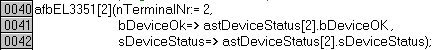 Fig.157: Addition of instances
Make sure that the "CnMaxIdxFb" constant declared in the main program (MAIN) is adapted to the desired number of terminals.
 Fig.158: Maximum number of EL3351s
Furthermore, the diagnostics of the terminals must be adapted. The code is adapted as standard for two terminals:
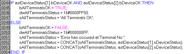 Fig.159: EL3351 diagnostics
For each new terminal
AND astDeviceStatus[2].bDeviceOKmust be inserted in line 61 and
sAllTerminalsStatus:= CONCAT(sAllTerminalsStatus, astDeviceStatus[2].sDeviceStatus);In line 70f. Here too, the number in square brackets always represents the number of the terminal.
The visualization consists of two placeholder visualizations. These can be used variably for an indefinite number of terminals. What both pages have in common is that they display the statuses of the devices and the channels. The page VISU_EL3351_BASIC is for the weight evaluation, while the page VISU_EL3351_CoE is for the processing of some CoE entries and for the evaluation of toggle bits.
The page VSU_EL3351 is the visualization page, which is to be used during operation. As standard it contains two pages of the placeholder visualizations in each case; hence, two terminals can be operated directly.
The visualization VSU_EL3351 must be selected in order to add new visualizations. Instances of the placeholder visualizations "VISU_EL3351_BASIC" and "VISU_EL3351_CoE" can be added using the "Visualization" button.
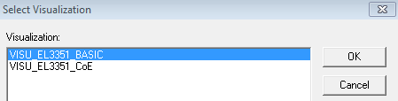 Fig.160: Addition of visualizations
The instance for the respective terminal must be selected as the placeholder by double-clicking on the added visualization.
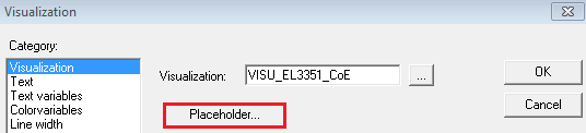 Fig.161: Placeholder selection button
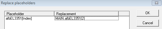 Fig.162: Replacement of the placeholder
For a better display the "Fixed" property can additionally be selected by double-clicking on the newly added visualization. This causes the size of the visualization to be adapted to the original size.
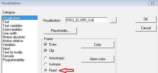 Fig.163: Selection of "Fixed"
In order to ensure that the page for editing the CoE parameters during operation only appears when the "Go to CoE Settings" button is pressed, an Invisible variable can be set in the Variables field of the visualization. The complete entry must look like this:
NOT MAIN.afbEL3351[3].bVisuZoomThe number in brackets represents the number of the terminal.
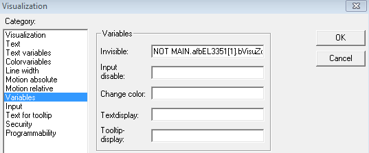 Fig.164: Setting the variable for invisible
As soon as the modified program has been translated it must be rescanned in the system manager.
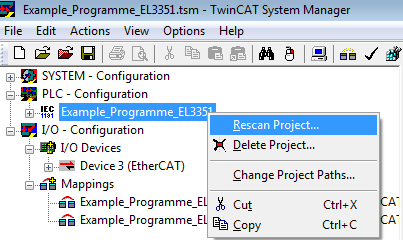 Fig.165: Rescanning the project
After that the required variables for linking the inputs and outputs are available.
The following overview shows the assignments of the variables:
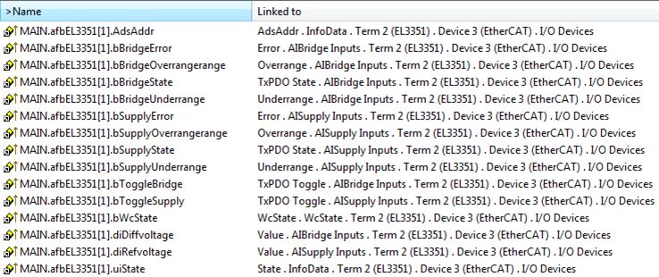 Fig.166: Assignments of variables for terminal
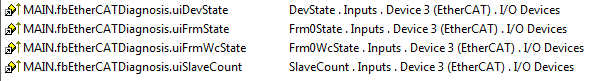 Fig.167: Assignments of variables for EtherCAT diagnosis