Pin assignment, display and diagnosis
EL3218
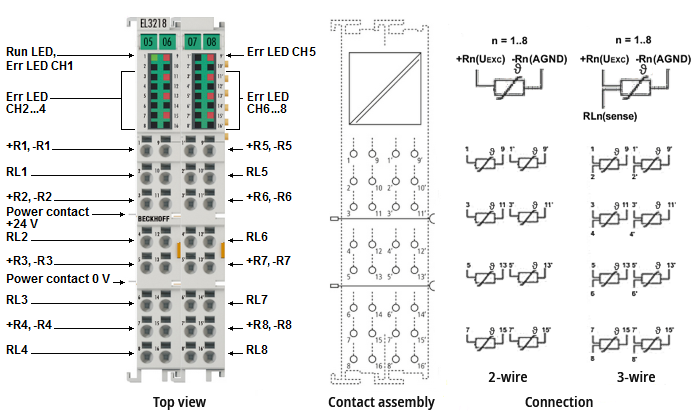 Fig.25: EL3218 pin assignment
EL3218 – pin assignment
Terminal points 1 – 16 (left side) | Terminal points 1' – 16' (right side) | ||||
|---|---|---|---|---|---|
Terminal point | No. | Comment | Terminal point | No. | Comment |
+R1 | 1 | Input +R1, current-carrying | +R5 | 1‘ | Input -R5, current-carrying |
RL1 | 2 | Input RL1, de-energized sense line | RL5 | 2‘ | Input RL5, de-energized sense line |
+R2 | 3 | Input +R2, current-carrying | +R6 | 3‘ | Input +R6, current-carrying |
RL2 | 4 | Input RL2, de-energized sense line | RL6 | 4‘ | Input RL6, de-energized sense line |
+R3 | 5 | Input +R3, current-carrying | +R7 | 5‘ | Input +R7, current-carrying |
RL3 | 6 | Input RL3, de-energized sense line | RL7 | 6‘ | Input RL7, de-energized sense line |
+R4 | 7 | Input +R4, current-carrying | +R8 | 7‘ | Input +R8, current-carrying |
RL4 | 8 | Input RL4, de-energized sense line | RL8 | 8‘ | Input RL8, de-energized sense line |
-R1 | 9 | Input -R1, current-carrying | -R5 | 9‘ | Input -R5, current-carrying |
n. c. | 10 | not used | n. c. | 10‘ | not used |
-R2 | 11 | Input -R2, current-carrying | -R6 | 11‘ | Input -R6, current-carrying |
n. c. | 12 | not used | n. c. | 12‘ | not used |
-R3 | 13 | Input -R3, current-carrying | -R7 | 13‘ | Input -R7, current-carrying |
n. c. | 14 | not used | n. c. | 14‘ | not used |
-R4 | 15 | Input -R4, current-carrying | -R8 | 15‘ | Input -R8, current-carrying |
n. c. | 16 | not used | n. c. | 16‘ | not used |
Notice | |
Increased measurement uncertainty with signal bundling of the AGND line In this terminal, the AGND contacts (signal return line -R) are connected in the terminal. |
 | Connection of analog RTD signal lines To ensure that the analog signals can be measured with as little interference as possible, also observe the notes in the chapter "Connection of analog RTD signal lines". |
EL3218 – LEDs
LED | Color | Meaning | |
|---|---|---|---|
RUN | green | This LED indicates the terminal's operating state: | |
off | State of the EtherCAT State Machine: INIT = initialization of the terminal or BOOTSTRAP = function for terminal firmware updates | ||
flashing | State of the EtherCAT State Machine: PREOP = function for mailbox communication and different default settings set | ||
single flash | State of the EtherCAT State Machine: SAFEOP = verification of the Sync Manager channels and the distributed clocks. | ||
on | State of the EtherCAT State Machine: OP = normal operating state; mailbox and process data communication is possible | ||
ERROR1 - 8 | red | Short circuit or wire break. The resistance value is in the invalid range of the characteristic curve. | |