Operating modes
The EL3255 supports three different operating modes:
- Freerun (filter on, timer interrupt)
- Synchron (filter off, SyncManager interrupt)
- Distributed-Clock-triggered (DC-Sync interrupt)
The operating mode required for the application is to be selected according to the following decision tree:
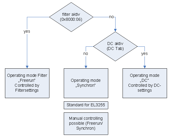 Fig.144: Operating modes of the EL3255
The terminal switches between the Freerun (filter on) and Synchron modes by activating/deactivating the filter via the index. The terminal remains in OP mode during this process. The changeover may result in longer sampling times and step changes in the process data until the filters have assumed a steady state.
DC mode can only be used when the filters are switched off. Likewise, it is not possible to switch the filters on in DC mode. The DC mode is parameterized via the DC tab in the TwinCAT System Manager.
Synchronous operation
In synchronous operation process data are generated frame-triggered, so that a new value is available with each PLC cycle. Synchronous operation is automatically used if the filters are deactivated and no DC is activated.
The minimum permissible cycle times are 500 µs in 5-channel mode and 300 µs in 2-channel mode.
DC operation
In DC mode the process data are requested via DC interrupt. As a result the temporal jitter between two frames is compensated and the sampling time is the same across the entire system, even over many EtherCAT devices.
The DC mode requires minimum cycle times of 500 µs in 5-channel mode and 300 µs in 2-channel mode. The "Input-based" mode automatically shifts the sync interrupt in such a way that the process data are ready shortly before the current process data cycle, therefore it is recommended as the standard setting for DCmode.
The measured value is typically read 500 ± 200 ns after the SYNC1 interrupt. There must be a temporal gap of 20 µs between SYNC0 and SYNC1.
Filter operation (FIR and IIR), Index 0x80n0:06, 0x80n0:15
The EL3255 is equipped with a digital filter which, depending on its settings, can adopt the characteristics of a Finite Impulse Response filter (FIR filter), or an Infinite Impulse Response filter (IIR filter). The filter is deactivated by default. Please observe the following note regarding activation with index 0x8000:06.
 | Activation of the filter with index 0x8000:06 and setting of the filter characteristics via index 0x8000:15 The filter frequencies are set for all channels of the EL3255 centrally via index 0x8000:15 (channel 1). The corresponding indices 80n0:15 of the other channels have no parameterization function. |
FIR filter
The filter performs a notch filter function and determines the conversion time of the terminal. It is parameterized via the index 0x8000:15. The higher the filter frequency, the faster the conversion time. A 50 Hz and a 60 Hz filter are available.
Notch filter means that the filter has zeros (notches) in the frequency response at the filter frequency and multiples thereof, i.e. it attenuates the amplitude at these frequencies.
The FIR filter operates as a non-recursive filter.
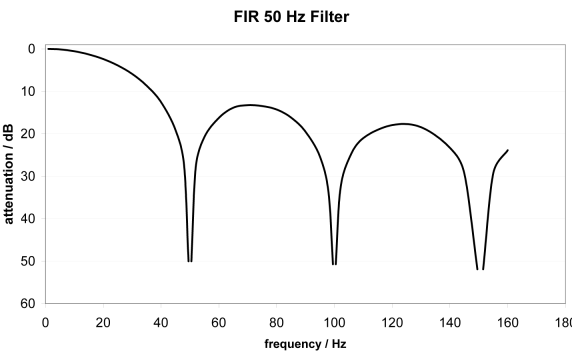 Fig.145: Typical attenuation curve of notch filter at 50Hz
|
Filter data for FIR filter | |||
|---|---|---|---|
|
Filter |
Attenuation |
Limit frequency (-3 dB) |
typ. conversion time |
|
50 Hz FIR |
> 50 dB |
22 Hz |
625 µs |
|
60 Hz FIR |
> 45 dB |
26 Hz |
521 µs |
IIR filter
The filter with IIR characteristics is a discrete time, linear, time invariant filter that can be set to eight levels (level 1 = weak recursive filter, up to level 8 = strong recursive filter).
The IIR can be understood to be a moving average value calculation after a low-pass filter.
Due to the FreeRun synchronization mode, the IIR filter operates with an internal cycle time of approx. 500 µs.
|
IIR filter |
Limit frequency (-3 dB), 5 activated channels |
|---|---|
|
IIR 1 |
400 Hz |
|
IIR 2 |
220 Hz |
|
IIR 3 |
100 Hz |
|
IIR 4 |
50 Hz |
|
IIR 5 |
24 Hz |
|
IIR 6 |
12 Hz |
|
IIR 7 |
6.2 Hz |
|
IIR 8 |
3.0 Hz |