Voltage-controlled mode
In voltage-controlled mode, multi-color LEDs must always be used with a series resistor to protect the LEDs against destruction. The commissioning and control of a multi-color Common Anode LED in voltage-controlled mode is described below. Unless stated otherwise, the step described must be performed for all EL2596 terminals with the multi-color Common Anode LED.
- Nominal/limit current of the LED in index 0x8000:02 “Target current” in the unit mA.
- Input voltage in index 0x8000:03 “Supply voltage” in the unit 0.01 V.
- Desired output voltage in index 0x8000:04 “Output voltage” in the unit 0.01 V. This value must be identical for all EL2596 terminals operated with the multi-color Common Anode LED.
- Set the operation mode in the CoE directory in index 0x8004:01 to “Voltage Control PWM”
- Set Predefined PDO Assignments to “PWM (with info data)”
- The PWM duty cycle can then be specified for each color (each EL2596) under “DOX PWM duty” → “PWM duty”. The higher the specified duty cycle, the brighter the color. The visible emitted color results from the mixture of colors in the multi-color LED.
- Check under “DOX Status” → “Status” whether the “Ready to activate” bit is 1.
- Activate the control under “DOX Control” → “Control” via the “Enable” bit.
- Switch on the LED output under “DOX Control” → “Control” by activating the “Output” bit.
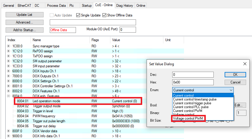 Fig.176: Operation mode setting “Voltage control PWM”
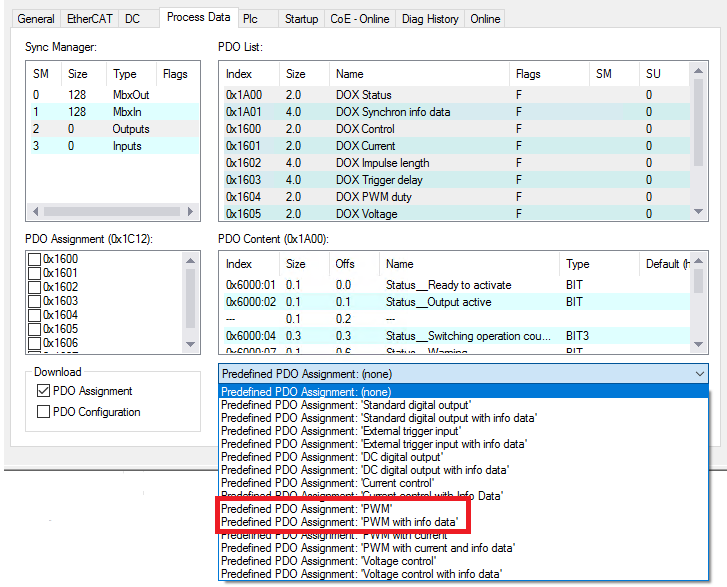 Fig.169: PDO setting “PWM (with info data)”
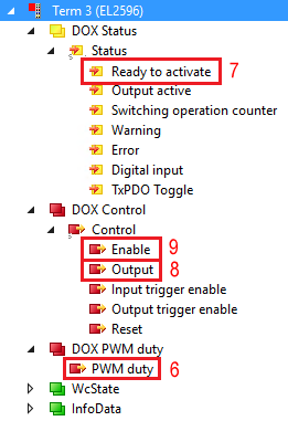 Fig.216: Activating the output in the operation mode “Voltage control PWM”