Sample program 1 - short-circuit detection (current-controlled)
Notice | |
Short-circuit detection in “Current Control” operating mode - A short circuit in the “Current Control” operating mode is detected if the current becomes greater than the maximum current specified in CoE 0x8000:02 at an output voltage that is less than the lower error limit for the output voltage. |

Program description and function
In addition to the classic use for controlling LEDs, the EL2596 can also be used for testing electrical contacts and other special applications. The current-controlled LED output can detect short-circuits or general current changes within a few milliseconds, display them as an error message and, if necessary, switch off. The test specimen to be tested, for example an electrical contact, must be connected potential-free to the LED output (connections 1 and 9).
In this sample, a device is connected to the EL2596-0000 (FW03), which in the normal state after enabling the output conducts a quiescent current of about 100 mA. If a short circuit also occurs, an error message is generated and the LED output of the EL2596 switches off after a short time.
The current/voltage curve during the short circuit can be seen in the following scope recording. The values “Output-Current” and “Output-Voltage” are read from the info data of the terminal. The time required to completely switch off the output is about 3 ms, the current increases briefly to approx. 700 mA.
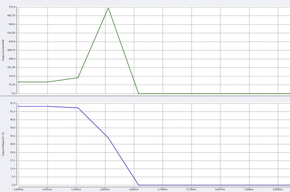 Fig.236: Time for detection of a short-circuit
With this sample program, a short circuit can be detected at the LED output with the help of the EL2596. For this purpose, the EL2596 outputs a specified current at the LED output (operation mode: “Current Control”). If a short circuit is detected at the LED output, an error message is generated, which can be read and processed with this sample program.
For this purpose, as described in the chapter Commissioning the values for the supply and output voltage, as well as the maximum output current must be specified in the CoE data.
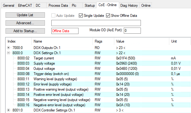 Fig.145: Setting current and voltage values in the CoE
The specified output values are then output at the output of the LED terminal. “Current Control” mode must be selected as the output mode (CoE index 0x8004:01).
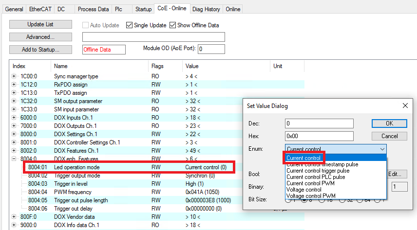 Fig.147: Selecting the “Current Control” operation mode
“Current Control (with info data)” is used as the Predefined PDO.
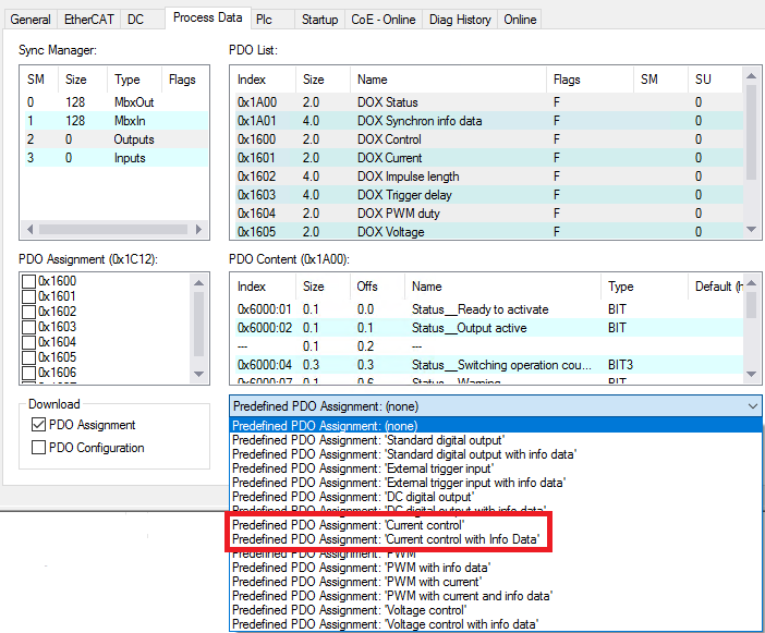 Fig.148: Selection of the Predefined PDOs “Current Control with info data”
In the sample program, diagnostic data are read from the diagnostic messages of the terminal. To do this, the NetID of the EtherCAT network and the ID of the EL2596 must be specified in the global variable list (GVL).
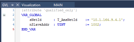 Fig.240: Sample program 1 - GVL
The NetID can be displayed in TwinCAT under the EtherCAT Master on the “EtherCAT” tab. The ID must be specified in the GVL as sNetID in inverted commas as a string.
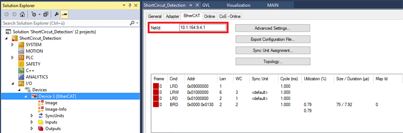 Fig.241: Displaying the NetID
The ID of the slave can also be found in the EtherCAT master. The “Online” tab must be selected in order to do this. This value must then be specified as nSlaveAddr.
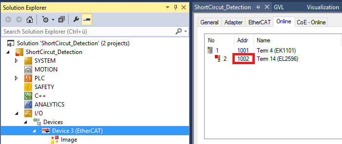 Fig.242: Displaying the slave address
The sample program can then be started. To use the sample program, the included visualization should be opened.
- If the program is started and the terminal is not in an error state, “ReadyToActivate” is active and the lamp in the visualization is green.
- The desired current at the output must be set in the “Set Output Current” box. This can also be changed while the short-circuit detection is running.
- The short-circuit detection can then be started in the visualization via the “Start” button.
- The output is then switched on from the PLC, so that the “Output” lamp also turns green.
- The “Output Voltage” and “Output Current” text boxes display the present values of the output.
- If a falling edge occurs on the “ReadyToActivate” bit in the PLC program, the reading of the diagnostic information from the CoE objects 0xA000 and 0x10F3 is started. The output switches off immediately.
- If a short circuit has occurred, this is recognizable from the diagnostic data and the “Shortcircuit” lamp in the visualization lights up red.
- If there is no longer a short-circuit at the LED output, the EL2596 must be reset manually via the “Reset” button, which is linked to the “Reset” bit of the EL2596.
- The LED output is then reactivated.
- The short-circuit detection can be stopped manually via the “Stop” button; the LED output is then switched off.
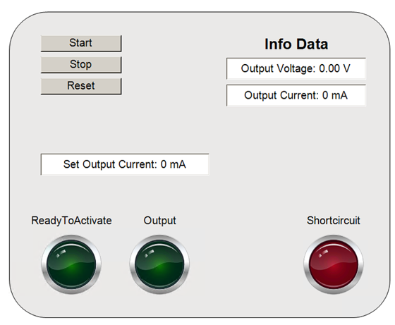 Fig.243: Sample program 1 - Visualization
 | Limiting the peak current in case of short-circuit If a short-circuit occurs at the LED output, currents >6 A can flow for a short time. In order to limit the peak output current, a resistor in the low ohm range can be connected in series with the component on which a short-circuit is to be detected. |