Notes on commissioning
Observe the following notes before commissioning:
Notice | |
Application from FW02/Revision0017 The documentation applies to the EL2596 only from firmware 02 with the revision -0017. With all older software revisions it is mandatory to perform a firmware update EL/ES/ELM/EM/EPxxxx and to update the ESI files in TwinCAT. |
- After a firmware update, the default parameters should always be reset. To do this, the password 0x64616F6C must be entered in the CoE object 0x1011:01.
- If the EL2596-xxxx is operated as a power source, no check is carried out when setting the LED current as to whether or not the connected LED is designed for the set current.
- The load must always be connected potential-free to the EL2596-xxxx with a two-wire connection. A connection to the input voltage is not permitted due to the internal current measurement.
- Operation of multi-channel LEDs
- If multi-channel/multi-color LEDs are to be operated with the single-channel EL2596-xxxx, a corresponding number of EL2596-xxxxs is required
- Operation in a common anode circuit with a series resistor, i.e. in voltage mode, or without a series resistor in current-controlled mode with external supply is possible as described in Operation of a multi-color Common Anode LED
- Operation in a common cathode circuit is not possible.
- Short cable lengths are recommended for high-precision control of the LED lighting.
- The EL2596-xxxx must always be supplied with power via the connection contacts 6, 7 or 8 and 14, 15 or 16.
Contacts 6, 7 and 8 and 14, 15 and 16 are each connected internally.
The terminal is not supplied via the power contacts. - Only regulated power supply units should be used as power supplies.
- The use of an EL9570 is recommended for a power supply with voltage peaks. The 24 V supply can be smoothed via the passive buffer capacitor terminal.
- The operating range is limited by three parameters:
- the maximum continuous output current, which is limited by internal components
- the maximum output voltage of the terminal
- the maximum output power of 14.4 W, which correlates with the internal power loss. The internal power dissipation in mW can be checked in the CoE object 0xF900:13.
- If currents are to be operated above the nominal current of the LED in a pulse mode, a higher specification is necessary for the output voltage in the CoE parameter 0x8000:04 due to the non-linear behavior of LEDs and the current control capability of the circuit.
- In the PDOs, all times (pulse length, delay, etc.) are specified in the unit 1 µs. These times are specified in the unit 0.1 µs in the CoE parameters. The resolution of the times in the PDOs can be reduced to 100 ns (0.1 µs) with the CoE parameter 0x8002:31 “Pulse resolution 100 ns”.
- If the predefined PDOs are selected with “info data”, internal data of the EL2596 can be mapped in order to monitor the values. The variables to be displayed can be selected in the CoE parameters 0x8002:11 and 0x8002:19.
- The “Ready to activate” bit must be active in order to be able to operate the LED. This is only the case if no errors or warnings are pending. (see Diagnostics)
- Especially in the pulsing modes leakage currents can occur which cause the connected LED to glow. To avoid this glow, the "Enable" bit must be deactivated if the LED output should be inactive.
- No wire break detection is possible in pulsing modes.
- External ventilation
- The ZB8610 fan cartridge can be mounted under the terminal. It reduces the internal temperature by approx. 20 °C. The internal temperature of the terminal can be viewed in the CoE 0xF900 or via the PDO InfoData. It is usually approx. 30 °C above the ambient temperature without a fan module.
- EL2596: For demanding applications with high power requirements, it may be useful to mount a fan cartridge under the terminal to support cooling.
- EL2596-0010: For operation of the 48 V variant EL2596-0010, a ZB8610 fan cartridge is mandatory to ensure that the terminal does not exceed the maximum allowed internal temperature.
- The parallel connection of several EL2596-xxxx for the purpose of increasing the current through one or more LEDs is not permitted due to the internal circuit in the EL2596-xxxx.
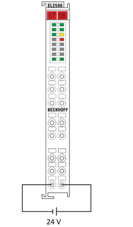 Fig.139: Power supply
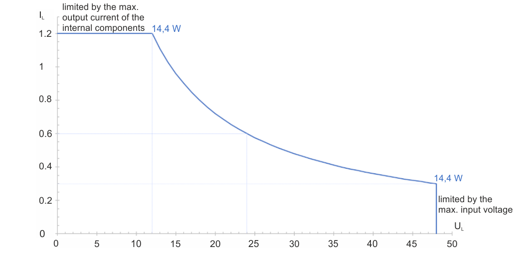 Fig.140: EL2596 operating range in Current Control and Voltage Control Mode
Time behavior in continuous light mode
The time behavior in continuous light mode is illustrated in the following figure.
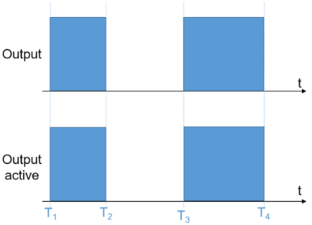 Fig.141: Timing - Continuous light
- T1 and T3: Switch-on times
- T2 and T4: Switch-off times
- In the case of continuous light, the signal “DOX Control” → “Control” → “Output is switched directly through to the driver stage”.
- The status is returned as feedback via “DOX Status” → “Status” → “Output active”.
Time behavior in pulse mode
The time behavior in a pulse mode is illustrated in the following figure.
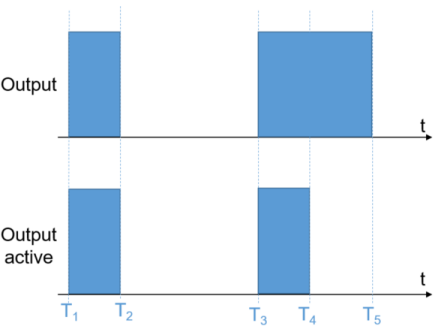 Fig.142: Timing - Pulse
- T1 and T3: Switch-on times
- T2 and T5: Switch-off time of the output bit
- T4: Switch-off time of the LED
- The LED output is switched on as soon as the output bit is set to TRUE.
- If the output bit is set to FALSE before the specified pulse length expires, the LED is also switched off
- If the output bit is TRUE for longer than the specified pulse length, the LED is switched off after the expiry of the time (T4 - T3). T5 then no has no further influence on the output.
The time behavior in pulse mode with an external trigger signal is illustrated in the following figure. Two different cases of the output of a pulse by trigger input are shown.
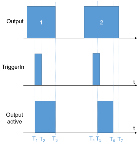 Fig.143: Timing - External trigger
In order to set the LED output, Input trigger enable must be activated in addition to the Output bit in order to enable the trigger function.
Case 1 – no delay:
- Output and Input trigger enable are already enabled at T1 and the external trigger event is detected.
- Output active is set immediately, as no output delay is set.
- After the specified pulse length T3 - T1, or if the output bit is set to FALSE, the LED output is also reset.
Case 2 – with delay:
- Output and Input trigger enable are already enabled at T4 and the external trigger event is detected.
- Output active is set for the specified pulse duration T6 – T5 after expiry of the specified delay time.
- The resetting of Output at time T7 has no effect on the output, since the output time has already expired.